How to interface 16X2 LCD with PIC16F877 microcontroller
Apr 05, 2016 By Karthik
This Post will cover interfacing of 16X2 character LCD with PIC16F series microcontroller to display a message "Hello World!!". PIC16F877 is the most preferred microcontroller among hobbyist because of its wide range of features available at less cost. HD44780 is a commonly used 16X2 character LCD because it is easy to interface and compatible with various microcontrollers. so, in this tutorial we are going to interface HD44780 LCD module with PIC16F877 micrcontroller. Before Proceeding, read the datasheet of PIC16F877 to have a overview on it PIC16F877 .
HD44780 - Description
HD44780 has two lines of display with 16 characters per line. Each character is displayed in the 5X7 matrix block.It has 14 pins for interfacing with external device and it has two 8 bit register namely, instruction register and data register to store and execute the instruction code and data transfer. Some LCD's have extra two pins LED+ and LED- for backlight power adjustments.
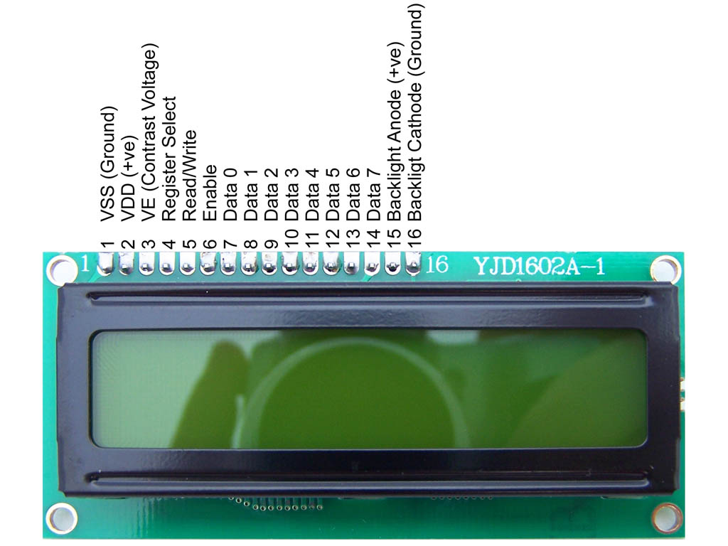
- Register Select (RS) - Logic '0' on RS pin is used to select instruction register and Logic '1' for data register.
- Read/Write (R/W) - Logic '0' to write in LCD module and Logic '1' to read from LCD module.
- Enable (E) - Logic '0' to disable LCD module and Logic '1' will enable it. Enable acts as the trigger for LCD operations.
- Data (D0 -D7) - Eight data lines for data transfer between LCD and microcontroller.
- Vdd & Vss - Power supply for LCD Module(+5V & GND).
- Vee - Contrast Adjustment of Display. It is connected through potentiometer to vary the voltage depending on contrast.
LCD Registers
- Instruction Register - IR stores the instruction code also called as LCD commands such as clear screen,cursor blink,cursor shift,etc., and address information for DDRAM and CGRAM
- Data Register - DR stores the data to be read from and write in DDRAM and CGRAM.
LCD Memory
- Display Data RAM (DDRAM) - It acts as the data buffer for the display. It stores the data to be displayed in LCD in the form of ASCII values. Each position in the LCD display has corresponding address location in the DDRAM. (0x80 - 0x8F) represents the address location for first line and (0xc0 - 0xcF) for second line.
- Character Generation ROM (CGROM) - The standard character pattern for 5X7 matrix to the corresponding ASCII Value is stored in CGROM. For example, ASCII Value '65' on certain position in DDRAM will display the character 'A' becuase of standard character pattern 'A' is stored in CGROM for ASCII Value '65'.
- Character Generation RAM (CGRAM) - It allows to create custom character by redefining patterns in CGRAM corresponding address locations.
LCD Instructions
For LCD commands to execute, the instructions has to be stored and processed from instruction register hence RS pin should be low for LCD commands. To write LCD commands, R/W should also be low. The 8-bit values on D0-D7 expresses the LCD commands. Enable E should be triggered ON & OFF to execute the LCD commands. The above table shows various LCD commands normally used in LCD operations.
Connection Diagram
Connection Diagram is captured using Proteus ISIS. It is a simulation based IDE here you can simulate and verify your design before implementing it in hardware design.
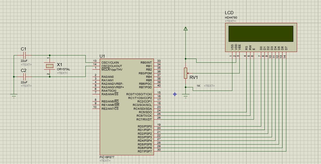
Data Pins (D0_D7) are connected to PORTD. If you want to save your I/O pins of microcontroller you can choose LCD 4-bit mode operations. (D4-D7) are used as data lines for 4-bit mode operation.Control Pins (RS,R/W,E) are connected to pin 5,6,7 of PORTC respectively. +5v and Gnd are connected to Vdd and Vss Respectively. Vee is connected through 1k variable resistor for contrast adjustments. For microcontroller, external crystal oscillator of frequency 11Mhz is used.
LCD Program
There are various IDE's available for PIC microcontroller source code development like MPLAB,micro C,etc., Microchip's MPLAB IDE is mostly preferred. Similarly, Hitech C compiler was used by hobbyist previously but nowadays XC8 complier has become more popular. Here we going to use MPLAB IDE with XC8 compiler. Download and install the latest version of IDE and compiler.

- Choose project as standalone project
- select PIC Family and device PIC16F877
- select hardware tool for programming and debugging
- select XC8 compiler
- Specify Project name and Folder then click Finish
Configuration Bits
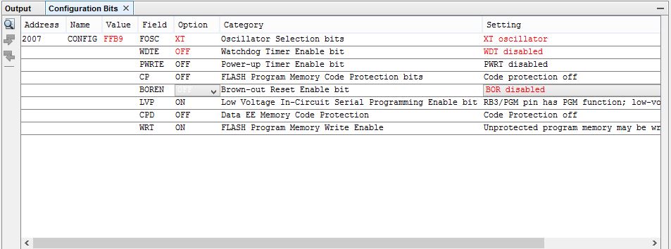
Configuration bits is presetting certain configuration of microcontroller before using it. For example, interfacing LCD doesn't require Watch dog timer So we can disable it before programming microcontroller. Specify the required configuration depending on your application need and click generate code to output. Copy the code and paste it in a header file named "configuration.h". Include the header file in your LCD source code.
LCD Initialization
Thumb rule in PIC programming is TRIS register for direction, PORT register for input and LAT register for output. But in midrange MCU, PORT register is used for both input and output. Logic '0' on TRIS register makes the port output and Logic '1' makes it input.
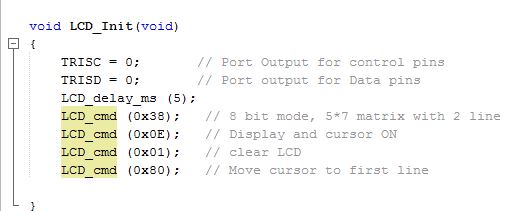
The direction of PORTD and PORTC are assigned as output by Logic '0' in TRIS register of respective ports.Because, Data and commands are send from the MCU to LCD module.For an LCD module to get initialized properly it needs some delay around 5ms. This makes the voltage level of LCD module to become stable.Then we have to set the entry level function of LCD. Here we are going to use 8-bit mode operation and use 5X7 matrix.From LCD command table, 0x38h will set the entry level function for 8 bit mode and 5X7 matrix. Write the LCD command to make Display ON, clear display and set Cursor position.
Routine to write LCD commands and LCD data to 16X2 LCD module are same except the RS Pin selection for data and instrcution register. See the source code for more LCD functions.
Main Program

Include the LCD header file in your main program. Initialize your LCD module by calling LCD Init function and Print the message "Hello World !!" by using LCD data write function. you can also move the cursor position by using DDRAM address. Send the DDRAM address of respective position as commands to LCD cmd write function and your cursor will move to the respective position. For every read and write operation include some delay for stable operation of LCD module. Use while(1) for infinite loop operation. Save and build the source code to generate hex file for your application. Program the hex file in your PIC16F877 and run it!

Comments
BBCode Tags
| BBCode | Rendering |
|---|---|
| [b]bolded text[/b] | bolded text |
| [i]italicized text[/i] | italicized text |
| [u]underlined text[/u] | underlined text |
|
Auto link already enabled. |
http://example.org |
|
Auto image already enabled. |
 |
| [code=php]<?php echo 'Hello!'; ?>[/php] | |
| [quote]quoted text[/quote] | quoted text |
|
[list] [*]Entry 1 [*]Entry 2 [/list] |
|