Graphing UART Data with LabVIEW Example using MSP430
Mar 31, 2016 By justin bauer
This post will cover how to start a new LabVIEW project and graph some simple data from the COM port on the TI MSP430 launchpad.
LabVIEW is by far the easiest and most suitable program for graphing and analysis. I have used several GUI builders such as Qt Desktop, Qt QML, C# Visual Studio, python matplotlib, and Java Swing - all of which still do not provide the ease-of-use and flexibility that LabVIEW provides out of the box. Being able to quickly debug and showcase your embedded platform is made easily using LabVIEW. However, its certainly not cheap and a lot of its GUI elements appear antiquated. It is difficult to make a LabVIEW GUI without it being obvious that it was written in LabVIEW. Some of the programing aspects and methodologies are also completely different then using a traditional programming language. You may find yourself aggravated at first during the transition, but it can be rewarding at the end and makes you a more flexible programmer.
LabVIEW (short for Laboratory Virtual Instrument Engineering Workbench) has been around for long time time of 30+ years. National Instruments, the creator of LabVIEW, has had 30 years to hone their software to what it is today. The GUI components may look old and antiquated, but they work beautifully.
LabVIEW is primarily geared towards Windows users with some concessions given to linux users. You can apparently build apps on linux using their development environment. I haven't tried it yet, so you should maybe check out their whitepaper. I will be using Windows.
LabVIEW Setup
Chances are that you won't have access to LabVIEW as a hobbiest. They do have a 45 day trial available. Student editions are also available and most universities have copies. You can also try convincing your workplace in purchasing a license. They start at $999 as of this writing.
I will be using LabVIEW 2013 in this post. Prior editions such as 2012 and 2009 should have no problem importing the files.
I am going to assume that the runtime environment is already installed. You will need to download and install the Virtual Instrument Software Architecture (VISA) from NI here since we will be utilizing the COM port on your computer. You will also have to download and install NI Serial. I will also be using "NI Inspired Custom Control Suite" that makes the generic controls look much nicer. I recommend that you install this using the VI Package Manager as documented on that website. You can still complete this tutorial by using the basic controls.
Creating the GUI
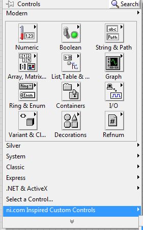
Make a new VI by clicking "File->New VI". Do a "File->Save As" and place it somewhere on your filesystem. I titled mine "Graph-Demo". Navigate to the block diagram (large white window) and right-click and goto "ni.com Inspired Custom Controls"->Waveform Chart. If you didn't' download this tool suite, you can just use the regular Modern->Waveform Chart. Note, do not use the graph use the chart.
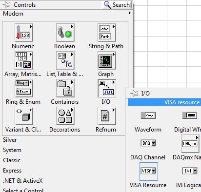
Next add a VISA by right-click->I/O->VISA Resource
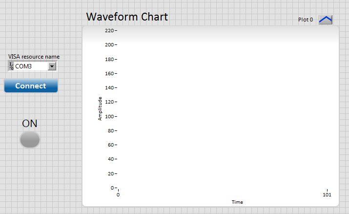
Next add a button by right-click->NI Custom Controls->Button (if not, goto Boolean->OK Button). Right-click the button and uncheck Visible Items->Label. Double-click into the button and change the text to "Connect". Right click and add a button (NI Controls->LED) or (Boolean->Round LED). Rename the label to "ON". Your GUI should look something like this.
Press Ctrl+E to goto the Block diagram easily.
Block Diagram
We are going to making 3 while loops. One will perform the I/O control, the other will do the background tasks such as graphing, and the other will handle the UI communication. We will be utilizing a design pattern called, "Publish-Subscribe", with state machines.
In order to save time and image clutter, I will be posting a few larger images from here on out that show the bigger picture rather than smaller ones. There will be a lot of drawing in this section.
Queue
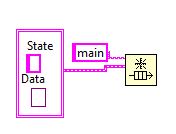
Press Ctrl+SPACE and search for "Obtain Queue". Place this somewhere. Right-click the little "name" input bubble on the left-hand side of the block and select "Create->Control". This should place an empty string nearby. Type "main" in the box. Next, make a cluster constant using the Ctrl+SPACE method as above.
In order to create a variant, place a "To Variant" on the diagram, hover over its endpoint and click "create constant". Now delete the "To Variant" block and move the variant and the string into the cluster. Change their label to "Sate" for the string and "Data" for the variant. Connect the cluster to the input of the queue.
Copy and paste that cluster that you just made above and place "M:Init" as the string input. Place an "Enqueue Element" block down and connect its queue input to the output of "Obtain Queue" block and the element input as the cluster output as shown:
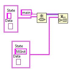
You have just created the basis of a design pattern where states can be changed via different threads by a lookup via the "State" string and pass in assocated data using the variant type. The variant allows you to typecast the data into anything you want as long as you know what the expected data type. Sometimes different threads are passing different types of data such as integers, strings, arrays, etc. Our system will comprise of 3 threads. One for the UI, ne for the background tasks, and one for the I/O serial comms.
UI Loop
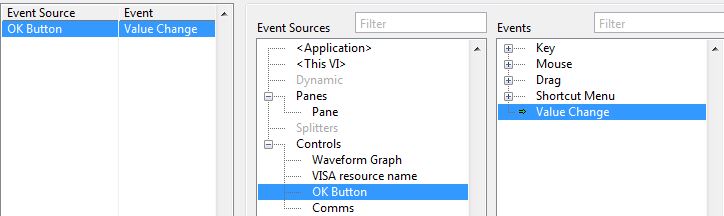
Create a Event Structure from your structures palette. Then place a while loop from your structures palette around the event structure. Right-click the event structure dropdown box and select "Add Event Case". Add an "onValue Change" Event to the "OK" Button. Place a boolean false block into the while loop and connect it to its stop condition in the lower-right hand corner.
Add an "Enqueue Element" block inside the while block's event structure and the string/variant structure made previously. The string should read "IO:Start". Now right-click on the boolean "ON" button and select "Create->Property Node->Value" as shown:
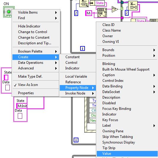
Place the value inside the IO loop and then right-click it and select "Change All to Write". Connect a boolean TRUE to it. Make the final connections as shown:
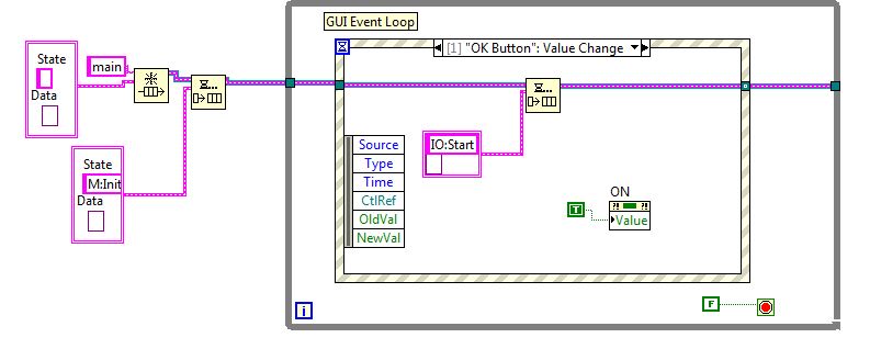
What you have just created in the UI Loop. This will run forever. When the OK button is pressed, it will send a message to the queue, "IO:Start", which will notify our IO loop to start communication.
IO Loop
Make another while loop below the last. Place a "Preview Queue" element. Connect it to the main queue. Create an "Unbundle by Name" block and have it connected to the "Preview Queue" element output. Place a "Match Pattern" block and an "IO:" string constant down. Connect the string constant to its regular expression input and the "State" cluster name to its string input. Place an "Empty String Path" to the output of the pattern block. Create a constant of a value of 2 as an input into "Preview Queue Element". Now create a case selector box. The output of the string path block must now connect to the selector.
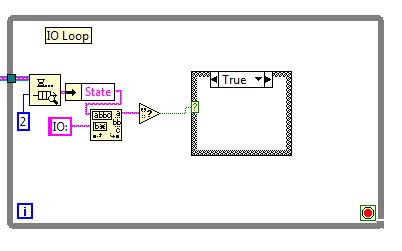
The above will look for any string containing the phrase "IO:" in it. If it does, then it passes it on towards a case selector for processing. If it doesn't after 2ms, it timeouts and continues.
Make your case selector look like the following by using:
- Match Pattern
- Dequeue Block
- Unbundle by Name
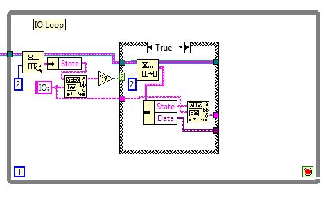
Another "Match Pattern" is used here to strip the matching "IO:" from the string. If the initial string does not contain this, then it will pass through to the "false" condition and nothing will happen.
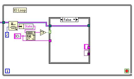
You can easily create constants by right-click the little squares and Create->Constant. You should have noticed that any line passed through a case selector MUST have the same data type connected to all of the available cases.
Expand your existing IO while loop and place another case selector in there. It's selector will be the output of the string from the previous case selector.
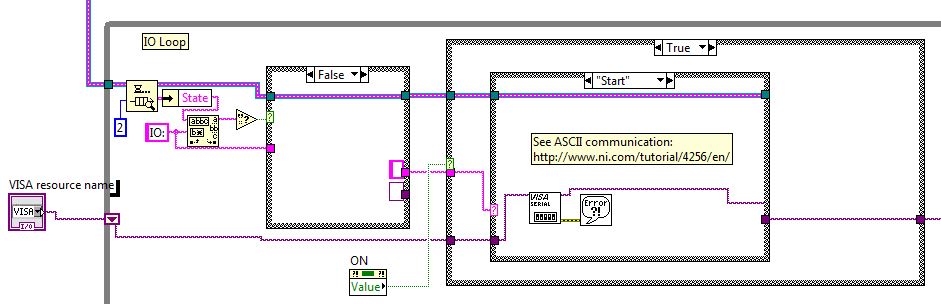
IO Initilization
This next section about setting up the serial port for ASCII mode can be found from NI here.This sets up the serial port for 9600 baud with new-line character (\n) termination. Notice how we are using a shift register for the VISA resource. This keeps the variable in memory for the duration of the program. Think of it as a static global variable.
Enclose the initialization routine with another case according to the ON value of the LED. This ensure that the IO loop doesn't run until the user presses the "connect" button. Make note of the inner case structure has a value of "Start".
IO Read
Click the arrow in the inner case structure to create a blank case and mark it as default by typing it in. This is where the IO loop will constantly poll the read buffer. Essentially this section will wait until a new line character (\n) is read. Tell it to read up to 255 bytes before terminating. This will terminate the read and pass the data onto the queue:
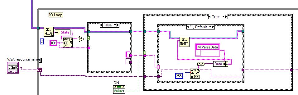
We typecast the string data from the serial buffer into a variant to be processed in the "Main" loop, which is designed by the "M:" in the state machine name.
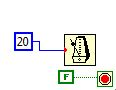
One last thing to do is to setup a sample period. For simplicity, lets hard code this to 20ms. Search for "Wait Until Next ms" block and make the loop run forever as shown:
Main Processing Loop
This loop is where the data will be analyzed and written to the graph. Copy and past the first portion of the IO loop into the main loop state machine and swap out the text string from IO: to M:.
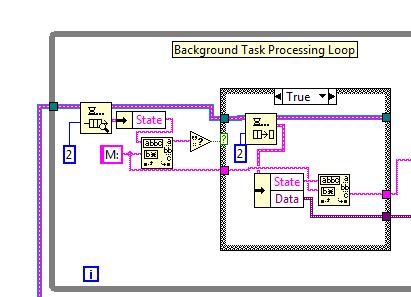
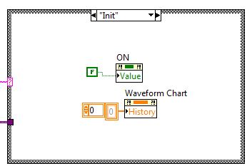
Make a case structure with two cases, "Init", "Parse Data", and "Default". In the Init loop, simply clear the WaveForm Chart Data and set the LED to OFF. The chart can be cleared by using "History Data" property node, right-click its input and selecting "create constant" and assigning it to an array of 0s.
The parse data portion retrieves the data from the queue, typecasts it back to a string, and uses "Decimal String to Number" block to convert the string to a number to be charted. Ex: "36" => 36.
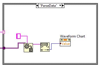
The waveform chart plots a new datapoint on the Y-Axis and increments the X-axis by one every time. X-axis represents the sample point.
Putting it all together looks like this:
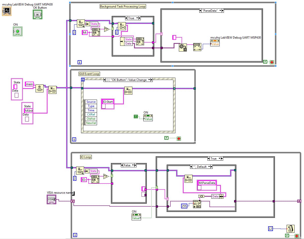
Reminder - You can easily download the VI by clicking on the github source link on the sidebar!. Press the Start button in LabVIEW to try out the VI. Nothing should be plotted to the graph just yet since it is not receiving any data.
Embedded Firmware
I'm going to be using the MSP430 Launchpad in easily sending data up to LabVIEW to graph. You can learn on how to setup a project and the UART on this post: MSP4340 LaunchPad - Simple UART Config and Echo. I have added the following code to the main loop to utilize the printf function and routing its output from the debug console to the UART. I got this code from the TI Wiki
/*
 * ======== Standard MSP430 includes ========
 */
#include <msp430.h>

/*
 * ======== Grace related includes ========
 */
#include <ti/mcu/msp430/Grace.h>

/*
 *  ======== main ========
 */
#include <stdio.h>
#include <stdint.h>
#include <string.h>

int fputc(int _c, register FILE *_fp);
int fputs(const char *_ptr, register FILE *_fp);

int main(void)
{
    Grace_init();                   // Activate Grace-generated configuration

    // >>>>> Fill-in user code here <<<<<
    static uint8_t i;
    while(1){
	   while(!(IFG2 & UCA0TXIFG)); // Wait until TXREG is empty
	   printf("%d\n", i++);
		__delay_cycles(8000); //  delay a little bit
    }

}

int fputc(int _c, register FILE *_fp)
{
	   while(!(IFG2 & UCA0TXIFG)); // Wait until TXREG is empty
	   UCA0TXBUF = (unsigned char) _c;

  return((unsigned char)_c);
}

int fputs(const char *_ptr, register FILE *_fp)
{
  unsigned int i, len;

  len = strlen(_ptr);

  for(i=0 ; i<len ; i++)
  {
	while(!(IFG2 & UCA0TXIFG)); // Wait until TXREG is empty
    UCA0TXBUF = (unsigned char) _ptr[i];
  }

  return len;
}
The MCU will count up to 255 before rolling over. The LabVIEW read routine uses the linefeed character ('\n') to know when to stop sampling the buffer and pass it onto the graph. Without it, the graph would not populate correctly and you would have to hardcode the routine on when to stop reading.
Improvements
There are a lot of improvements that can be made on this basic program here is a short list:
- Have a button to toggle ON/OFF operation
- Error Handling of incorrect COM port
- Right now the LabVIEW program will crash if an incorrect port is chosen as you have might have already seen
- Configure to binary mode instead of ASCII to save on package size and time
Comments
BBCode Tags
| BBCode | Rendering |
|---|---|
| [b]bolded text[/b] | bolded text |
| [i]italicized text[/i] | italicized text |
| [u]underlined text[/u] | underlined text |
|
Auto link already enabled. |
http://example.org |
|
Auto image already enabled. |
 |
| [code=php]<?php echo 'Hello!'; ?>[/php] | |
| [quote]quoted text[/quote] | quoted text |
|
[list] [*]Entry 1 [*]Entry 2 [/list] |
|