STM32F3 Discovery Board Setup using Eclipse on Windows
Jun 10, 2016 By justin bauer
Jan 2017 Update: Install the AC6 IDE instead and save yourself a bunch of time.
Original: I decided to write short post about setting up the STMicro STM32F3-discovery board for Windows using Eclipse. I was hoping that I could get started pretty quickly using their board and just blink a few LEDs without using a code-limited IDE, but I was wrong and I spent quite some time figuring out where to look for a good resource to get started. I was fortunate to find some good resources on youtube and this blog
Steps:
Flashing
- Create a folder called
STM32on your computer somewhere. Place all of your downloads here - Download Eclipse Mars or later and extract it into your STM32 folder. Please note: Eclipse Neon at this time of writing WILL NOT work with the GNU ARM plugin. Please see this discussion. Basically the developers of Eclipse moved some things around and the plugin is broken until v3 is released. You can run the EXE directly without having it install files to the registry which is pretty neat and handy. You may also need to install the Java JRE 1.8
- Create another folder called
workspaceinside yourSTM32folder. When launching eclipse, it will ask you where to put your workspace. Mine for example is:C:\Users\justin\Documents\STM32\workspace - Download GNU Tools for ARM Embedded Processors.
- Download Core Utilities. Run the installer and be sure to change the installation path to
C:\Coreutils\or some other location that is convenient for you. Once this is finished running, make sure that windows added the install location to your system environment path! It should do this automatically, but if you receive any errors in Eclipse later on such "Cannot find 'make'", then this would be your problem. - Download OpenOCD which is the debugger that we will be eventually using
- Download and run the installer for STLinkv2 driver - STSW-LINK009. I then had to open up the device manager and right-click "Update Driver Software" over the STMLink USB port and tell it to search for the driver. I had success by telling it to look online automatically. If that does not work, then manually browse to where the EXE placed the driver files. This is what your
STM32folder should now look like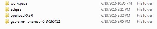
- Inside of Eclipse, click
Help->Install New Software. Select the "Mars" source in the "Work with" selection box and search forgdb. Check the box next toC/C++ GDB Hardware Debugging.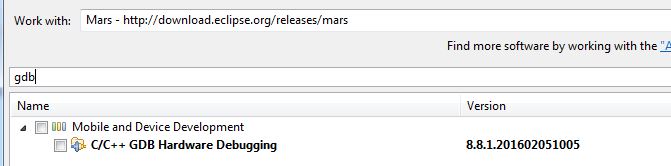
- Once the above is finished downloading and you have restarted, navigate back to the install software page and click the
Add...button and then copy/paste this url into the location box:http://gnuarmeclipse.sourceforge.net/updatesand title it "GNU ARM Eclipse Plug-ins". Wait for the files to populate and you should see a box populate. At the bare minimum, check the OpenOCD debugging and, Cross Compiler, and STM32Fx Project Templates. I just installed them all.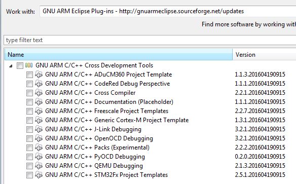 Restart the IDE once finished.
 - Make a new project inside of Eclipse.
File->New C Project. SelectSTM32F3xx C/C++ Project. I titled mine "STM32F3_Blinky". On the next page, select "Empty" project as the project content. Then click next. Leave the suggested folders as is. Select thebinfolder of your GCC GNU folder location and enter it under the toolchain path. Mine isC:\Users\justin\Documents\STM32\gcc-arm-none-eabi-5_3-160412\bin. Once the project is completed, go ahead and built it! - Click the
External Tools Configuration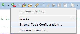
- Right-click on the
Programlisting and selectNewto create a new configuration. - Click
Browse File System...button and selectopenocd.exein the OpenOCD folder. Mine was located here:C:\Users\justin\Documents\STM32\openocd-0.9.0\bin-x64\openocd.exe - Make the
Working Directorylocation to your debug folder of your project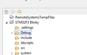
- Add the following to the
argumentsbox:
-f ../scripts/interface/stlink-v2.cfg
-f ../scripts/target/stm32f3x_stlink.cfg
-c "init; reset halt"
-c "flash write_image erase STM32F3_Blinky.elf"
-c "reset run; shutdown"
This invokes the OpenOCD debugger and loads the correct configuration for the STlink and our project (STM32F3_Blinky.elf"). Now run the program and you should see this (truncated for brevity) output indicating a successful flash
Open On-Chip Debugger 0.9.0 (2015-05-19-12:09)
Licensed under GNU GPL v2
For bug reports, read
	http://openocd.org/doc/doxygen/bugs.html
....
...
Info : device id = 0x10036422
Info : flash size = 256kbytes
Info : Padding image section 0 with 3 bytes
target state: halted
target halted due to breakpoint, current mode: Thread
xPSR: 0x61000000 pc: 0x2000003a msp: 0x2000a000
wrote 6144 bytes from file STM32F3_Blinky.elf in 0.847048s (7.083 KiB/s)
adapter speed: 1000 kHz
shutdown command invoked
Download the attached source zip to see an LED blink after succesful programming.
Debugging
-
Duplicate the existing tools configuration from above by right-clicking it and selecting
Duplicate. Name itSTM32 Debug. -
Paste this for the arguments.It is the same as the other configuration for flashing the chip, except it doesn't actually write and only enters into the programmer.
-f ../scripts/interface/stlink-v2.cfg -f ../scripts/target/stm32f3x_stlink.cfg -
Enter a new debug configuration
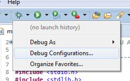
-
Double-click on
GDB Hardware Debuggingto create a new config. If you don't see this option, you may have forgotten to install the GDB plugin as shown in the beginning of this tutorial. -
Switch to the debugger tab and enter the GDB Command location to the
arm-none-eabi-gdb.exefrom the GNU Tools for ARM Embedded Processors download above. My location isC:\Users\justin\Documents\STM32\gcc-arm-none-eabi-5_3-160412\bin\arm-none-eabi-gdb.exe. Make the rest of your screen look like this:
-
Select the startup tab and make the inputs look like this:
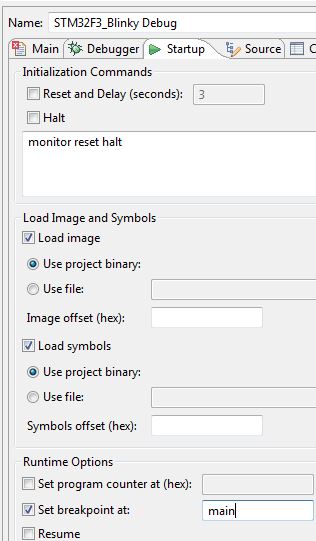
-
Click
Debugto finally enter debug mode!
If you don't want to download my "blinky" project, you can always place a few asm("nop"); in your main code to place a few breakpoints to test out the functionality.
Sample Blinky code
I created this code to simply blink one of the LEDS on the discovery board. I started this project using the default template for a new STM32F3 project. The system libraries should already be in the include path inside of Eclipse if you created the project via the GNU ARM project creater (File->New Project->STM32F3 Empty Project)
/**
 * Simple program to blink one of the LEDs on the STMF3 discovery board
 * @date June 2016
 * @author mcuhq.com
 */
#include <stdio.h>
#include <stdlib.h>
#include "diag/Trace.h"

#include <stm32f30x.h>
#include <stm32f30x_gpio.h>
#include <stm32f30x_rcc.h>

// Sample pragmas to cope with warnings. Please note the related line at
// the end of this function, used to pop the compiler diagnostics status.
#pragma GCC diagnostic push
#pragma GCC diagnostic ignored "-Wunused-parameter"
#pragma GCC diagnostic ignored "-Wmissing-declarations"
#pragma GCC diagnostic ignored "-Wreturn-type"

void delay (int a);

void main(int argc, char* argv[])
{
	// At this stage the system clock should have already been configured
	// at high speed.
	GPIO_InitTypeDef gpio;
	SET_BIT(RCC->AHBENR, RCC_AHBENR_GPIOEEN);

	// Configure one of the LEDs as a digital output
	GPIO_StructInit(&gpio);
	gpio.GPIO_Pin = GPIO_Pin_10;
	gpio.GPIO_Mode = GPIO_Mode_OUT;
	gpio.GPIO_Speed = GPIO_Speed_2MHz;
	GPIO_Init(GPIOE,&gpio);

  // Infinite loop
  while (1)
    {
		GPIO_WriteBit(GPIOE, GPIO_Pin_10,Bit_SET);
	    delay(500000);
		GPIO_WriteBit(GPIOE, GPIO_Pin_10,Bit_RESET);
		delay(500000);
    }
}

void delay (int a)
{
    volatile int i,j;

    for (i=0 ; i < a ; i++)
    {
        j++;
    }

    return;
}

#pragma GCC diagnostic pop

// ----------------------------------------------------------------------------
Comments
BBCode Tags
| BBCode | Rendering |
|---|---|
| [b]bolded text[/b] | bolded text |
| [i]italicized text[/i] | italicized text |
| [u]underlined text[/u] | underlined text |
|
Auto link already enabled. |
http://example.org |
|
Auto image already enabled. |
 |
| [code=php]<?php echo 'Hello!'; ?>[/php] | |
| [quote]quoted text[/quote] | quoted text |
|
[list] [*]Entry 1 [*]Entry 2 [/list] |
|