How to Create a Blinking LED project using Atmega16 microcontroller in Proteus - Step by Step with Pictures
Apr 06, 2016 By Anon
In this tutorial we will learn how make a simple LED blinking project using an Atmega16 microcontroller and how to simulate that project in proteus8 software . It's a pretty simple project . If you don't know how to use Proteus and MikroC , don't worry - I'm going to show you everything step by step. First you need to download two essential software packages called Proteus8 & MikroC pro for AVR .
Basic Concepts
In this tutorial, we will connect 5 LEDs to PORTB of Atmega16 microcontroller. Here all +(Positive) ends of LEDs will be connected with microcontrller's pins and the other end's will be connected to the ground (GND). The Microcontroller will configure its pins as general purpose Input/Ouput. The connection between the LEDs & microcontroller will be like this:
1. GND<<<<---LED1--->>>>RB0_Pin_of_Atmega16
2. GND<<<<---LED2--->>>>RB1_Pin_of_Atmega16
3. GND<<<<---LED3--->>>>RB2_Pin_of_Atmega16
4. GND<<<<---LED4--->>>>RB3_Pin_of_Atmega16
5. GND<<<<---LED5--->>>>RB4_Pin_of_Atmega16
So, when RB0 pin becomes High (providing 3.3v voltage), LED1 turns ON and when RB0 pin goes LOW (0 voltage), LED1 turns OFF. By changing the states (HIGH or LOW), we can arrange a system like this:
1.LED1_ON---LED2_OFF---LED3_OFF---LED4_OFF---LED5_OFF
//delay_500_miliseconds
2.LED1_OFF---LED2_ON---LED3_OFF---LED4_OFF---LED5_OFF
//delay_500_miliseconds
3.LED1_OFF---LED2_OFF---LED3_ON---LED4_OFF---LED5_OFF
//delay_500_miliseconds
4.LED1_OFF---LED2_OFF---LED3_OFF---LED4_ON---LED5_OFF
//delay_500_miliseconds
5.LED1_OFF---LED2_OFF---LED3_OFF---LED4_OFF---LED5_ON
...
In step 1, LED1 turns ON and others are OFF for 500 miliseconds. When all steps are complete, it's going to repeat again. Now the question is how do we get our microcontroller to do this?
Code
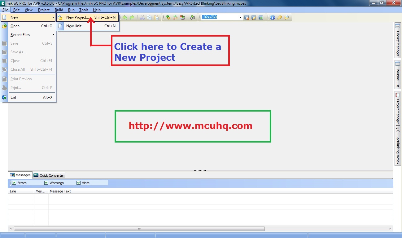
We will use MikroC pro for AVR compiler to write our code. Lets create a project in MikroC.
Please follow the instructions ..
MikroC Code
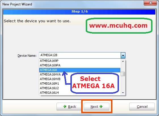
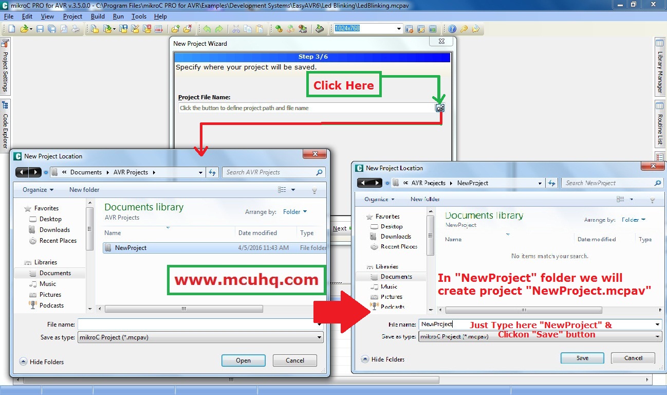
Step 1:
Step 2:

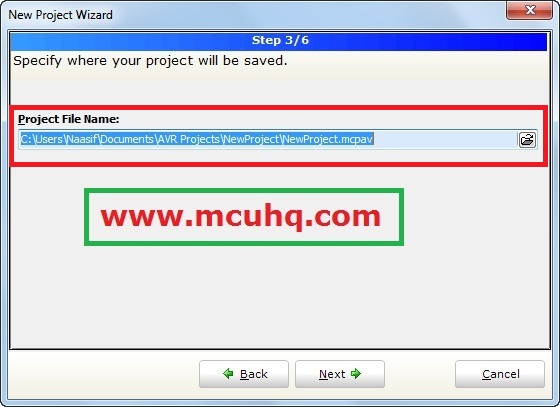
Step 3:
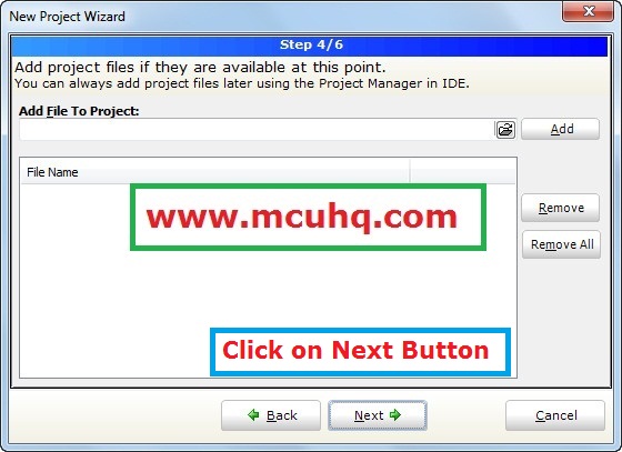
Step 4:
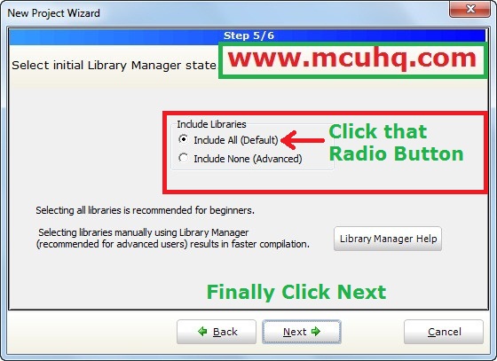
Step 5:
Step 6:
Step 7:
Step 8:
Step 9:

Step 10:
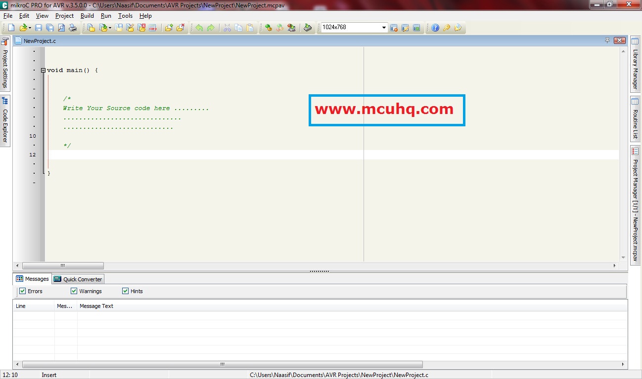
Here we will write our source code . You can download the source code from download link at the top of this page or you can copy and paste from here
Source Program
    void main() {
          DDRB.F0=1; // setting up RB0 as output
          DDRB.F1=1;  // setting up RB1 as output
          DDRB.F2=1;   // setting up RB2 as output
          DDRB.F3=1;   // setting up RB3 as output
          DDRB.F4=1;    // setting up RB4 as output


         while(1){
             PORTB.F0=1;
             PORTB.F1=0;
             PORTB.F2=0;
             PORTB.F3=0;
             PORTB.F4=0;
             Delay_ms(500);  // turning ON LED 1 for 500 milisec

             PORTB.F0=0;
             PORTB.F1=1;
             PORTB.F2=0;
             PORTB.F3=0;
             PORTB.F4=0;
             Delay_ms(500);  // turning ON LED 2 for 500 milisec

             PORTB.F0=0;
             PORTB.F1=0;
             PORTB.F2=1;
             PORTB.F3=0;
             PORTB.F4=0;
             Delay_ms(500);  // turning ON LED 3 for 500 milisec

             PORTB.F0=0;
             PORTB.F1=0;
             PORTB.F2=0;
             PORTB.F3=1;
             PORTB.F4=0;
             Delay_ms(500);  // turning ON LED 4 for 500 milisec

             PORTB.F0=0;
             PORTB.F1=0;
             PORTB.F2=0;
             PORTB.F3=0;
             PORTB.F4=1;
             Delay_ms(500);  // turning ON LED 1 for 500 milisec
         }
    }
A little description about Code
void main() {.......}
This is the code entry point when the microcontroller starts. void means it will return nothing.
while(1){........}
This will run forever while the microcontroller is powered. It is not going to stop until we disconnect the power.
DDR.X
DDR stands for "Data Direction Register". We are going to use this register to setup the individual pins as an output.
DDRB.F0 assigns the "0th" bit or pin 0 of the B register a value of 0, making it an output. This is opposite of the configuration of Microchip's PIC controllers where a 1 equals input and 0 equals output. If we were to use PORTB, we have to use the DDRB register .
1.DDRB.F0 // controls PORTB.F0 (RB0) pin
2.DDRB.F1 // controls PORTB.F1 (RB1) pin
...
If we set DDRB.F0=1, the RB0 pin will be configured as an output. If we set DDRB.F0=0, the RB0 pin will be configured as an input.
PORTB
Writing directly to the Atmega's port will set the voltage on that pin HIGH (3.3V) or LOW (0V)
1.PORTB.F0=1 // pin goes HIGH
2.PORTB.F0=0 // pin goes LOW
...
Function delay_ms(500)
This is a delay macro provided by the Mikro C compiler. The microcontroller wil execute a series of decrements to waste time until the delay time has been reached.
 PORTB.F0=0;
 PORTB.F1=1;
 PORTB.F2=0;
 PORTB.F3=0;
 PORTB.F4=0;
 Delay_ms(500);  // turning ON LED 2 for 500 milisec
Here the pin RB1 is ON and others are OFF . So this state will be continued for for 500 miliseconds .
Now it's time to compile our project
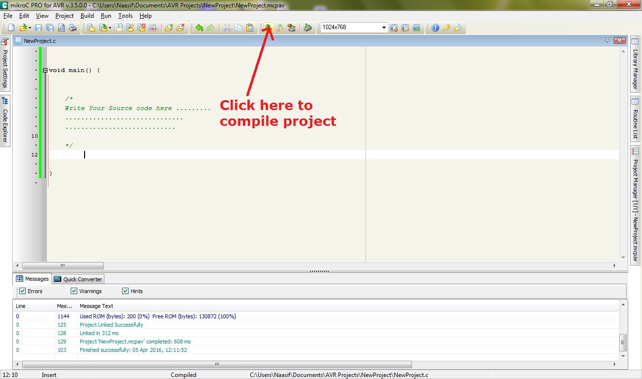
Getting the hex file
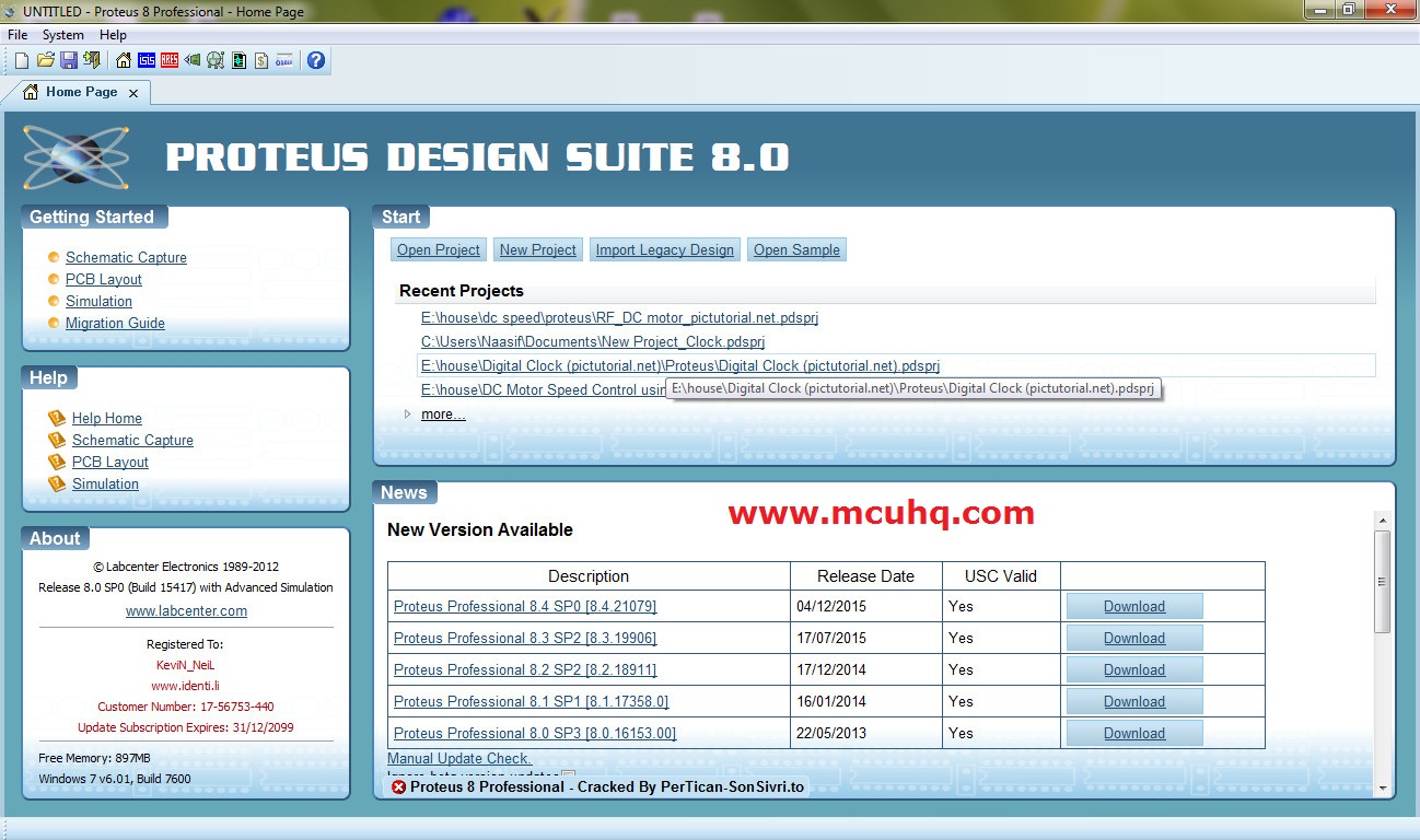
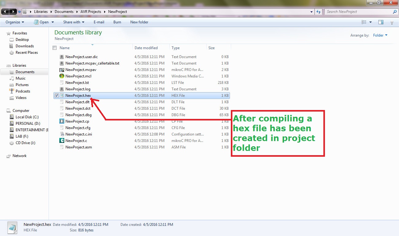 Now we need to create a simple circuit using Proteus8 .
Proteus Circuit
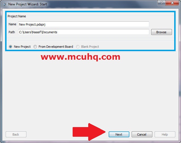
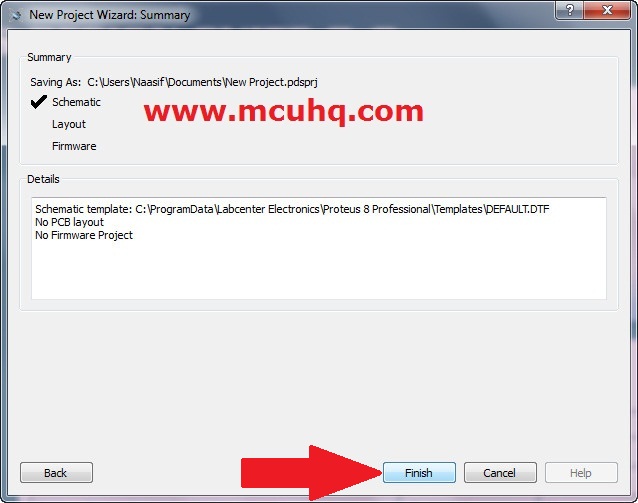
Step1:
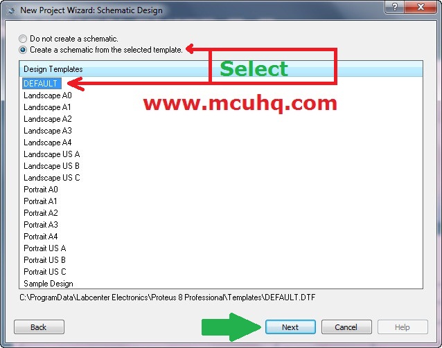
Step2:
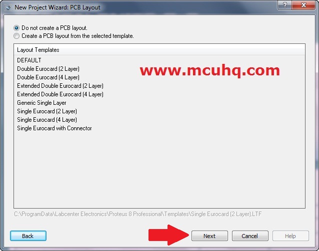
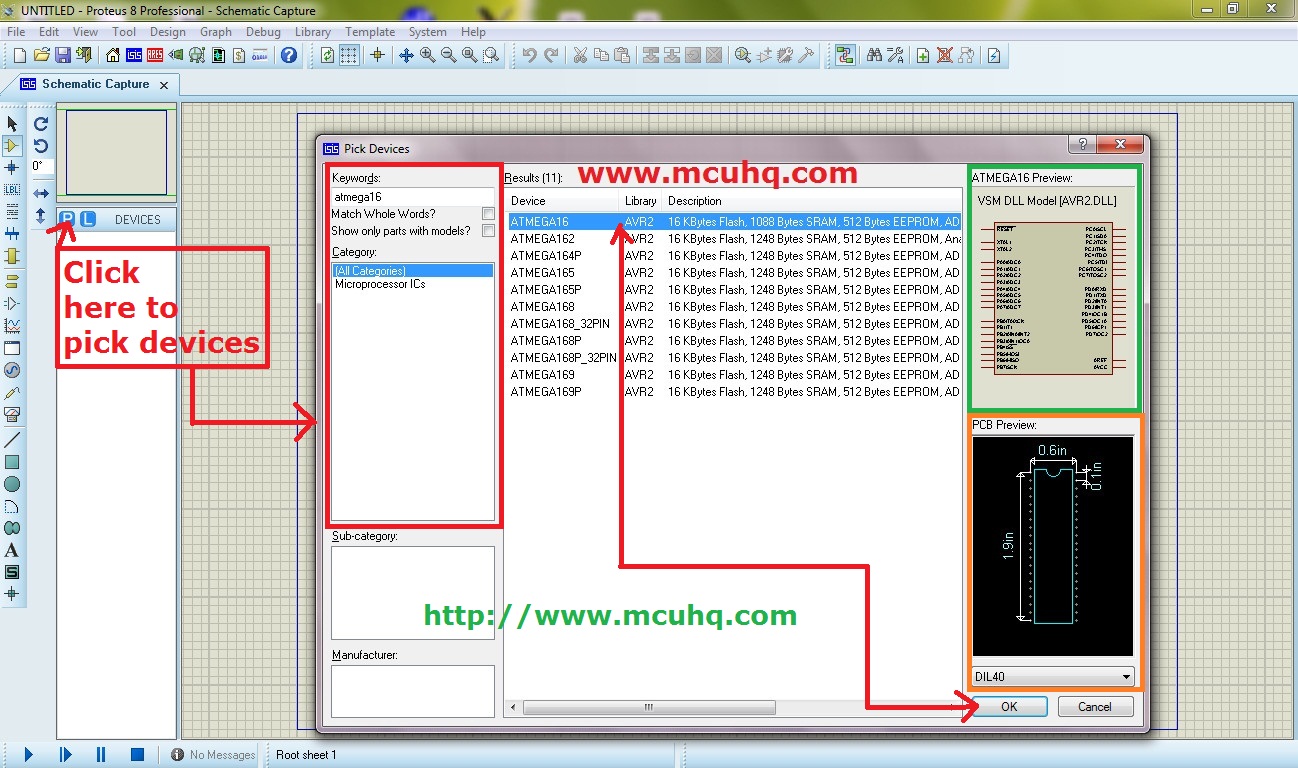
Step3:
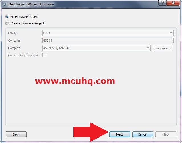
Step4:
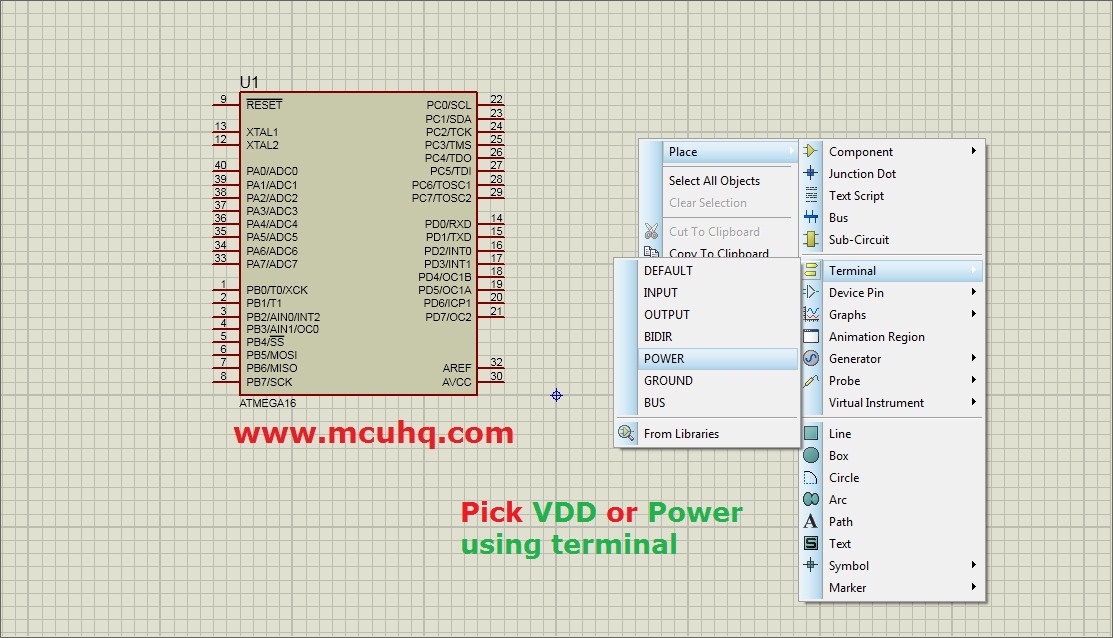
Step5:
Step6:
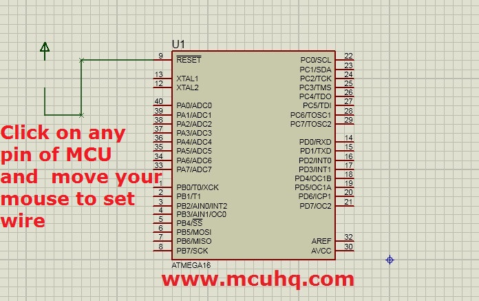
Step7:
Step8:
Step9:
Main Circuit
Click on the picture to enlarge
Just complete the circuit as I have done below.
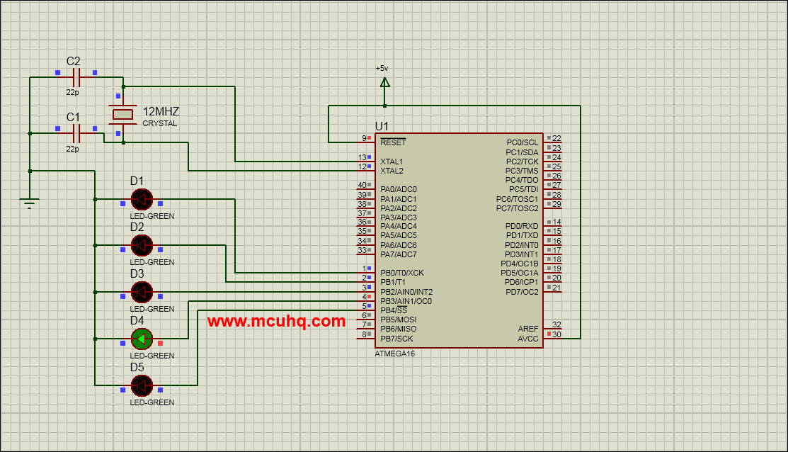
Schematic Overview
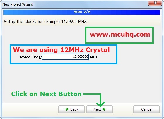
Here you can see we are using a 12MHz Crystal. The microcontroller uses this to base its internal clock. There are two type of clock: Internal and external. Add the crystal between the xtal1 pin & xtal 2 pin. You will have to add two 22pf capacitors in order to stabalize the crystal.
Double-click on the microcontroller to verify the following:
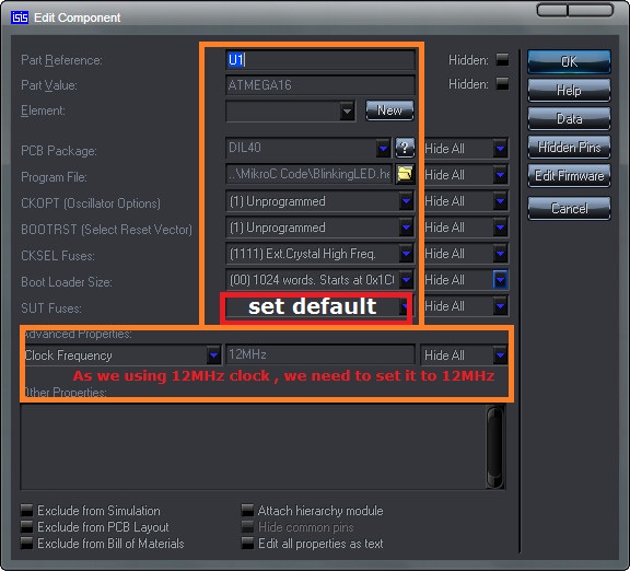 And click "OK" .
Now Load the hex file to the Microcontroller
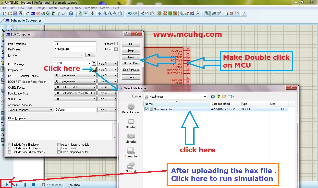
Run it .
Watch the Video
You can download this project from the download link .
Comments
BBCode Tags
| BBCode | Rendering |
|---|---|
| [b]bolded text[/b] | bolded text |
| [i]italicized text[/i] | italicized text |
| [u]underlined text[/u] | underlined text |
|
Auto link already enabled. |
http://example.org |
|
Auto image already enabled. |
 |
| [code=php]<?php echo 'Hello!'; ?>[/php] | |
| [quote]quoted text[/quote] | quoted text |
|
[list] [*]Entry 1 [*]Entry 2 [/list] |
|