MSP430 Launchpad - GUI Composer Example
Mar 28, 2016 By justin bauer
TI introduced a GUI tool to quickly help visual your embedded system. It works inside of the CCS IDE since v5.3. See the offical wiki documentation in order to learn more about the features. This post will be using the MSP430G2553 that comes with the Launchpad to demonstrate the powerful functionality of the GUI builder.
Often times embedded systems need to evaluated or debugged on its performance before production. This is usually accomplished by running the debugger and connecting to the target to watch variables or utilizing a few LEDs to indicate a response. The LED approach can soon become too limited as the project grows in complexity and the debugger approach can become too intrusive on the program flow to accurately convey information. A nice GUI is then programmed and connected to the target MCU to showcase its functionality and change variables on the fly without needing to modify the firmware (For example, modifying a motor's RPM). With GUI Composer, the work of creating a GUI and added firmware bloat to handle the Read/Write operations from the connected PC is already done! You can even distribute your GUI as a standalone app to windows users to easy demonstrate functionality.
Creating the Project
Open up CCS v5.3 or later. You must install the GUI Composer add-on and Grace before starting. You can do so by clicking on View->App Center and searching for both of these plugins and installing them.
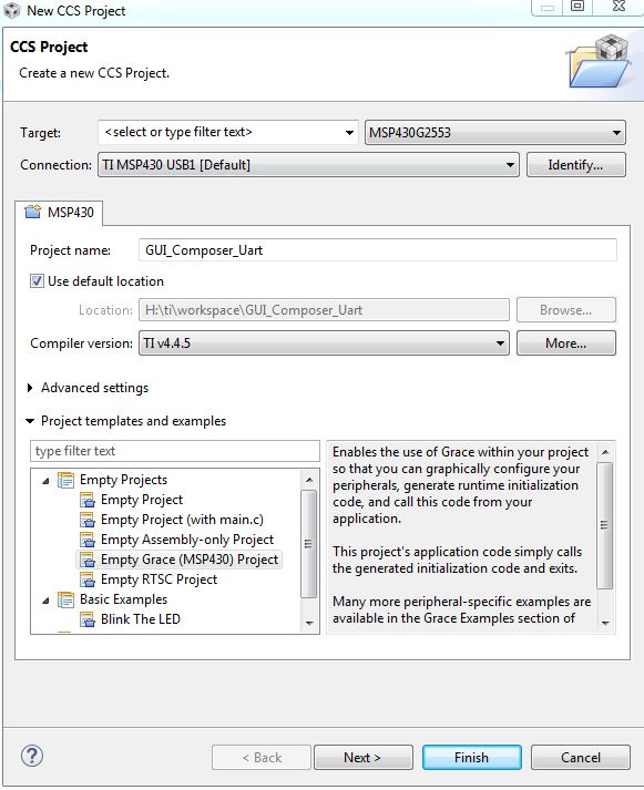
Click File->New CCS Project. Select the TI compiler, your target device (MSP430G2553 in my case), and highlight Empty Grace Project as the template.
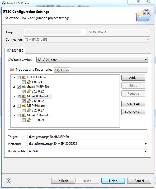
Then select the Grace checkbox and MSP430 Driver.
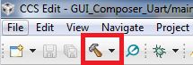
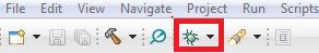
Then build the project to make sure everything is in working order by pressing the hammer button in the toolbar
You should see a Build Finished text string in your Console if it succeeded.
UART monitor
There are 2 ways for the GUI to relay data back and forth from the MSP430:
- Using JTAG
- Using a UART monitor
The JTAG method is the easiest method and requires no additional loaded software or overhead, however it requires a JTAG programmer to be installed on the Launchpad.
The UART method requires no additional hardware with the exception of a USB cable, but does entail programming a uart monitor to handle the incoming and outgoing requests from the GUI. TI does provide a demo monitor to use, but there is very little documentation on how it works and where to modify it. It is still a mystery as to how it read/modify/write from the on-board flash. More on this later...
In short, this is how the layers work according to docs
- CCS Debugger is used to translate Symbols to addresses -- You type in "Motor_RPM" variable in the GUI, but behind the scenes the debugger evaluates this to its actual address on the MSP430
- Writes to the target are done via JTAG or via a command to a target monitor -- JTAG supports data manipulation on-the-fly during program execution. Another option is to use a software method via the UART hardware module
- Data is requested by the GUI application -- The GUI is the "master" and initiates all interactions. The MCU is the "slave"
- JTAG or Serial connections are used -- Can use the JTAG and software method
UART Setup
Click on main.cfg in your workspace. Click the USCI A0 hardware block in the Device Overview tab or by selecting it in the dropdown menu
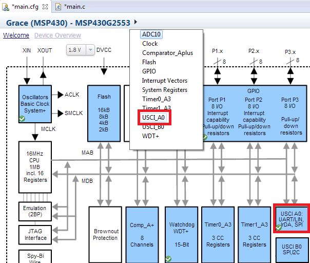
This configures the hardware UART to 9600 baud and utilizes the TX/RX pins. Note You may need to adjust the jumpers on your MSP430 launchpad to connect to the right pins. Look at J3 and orient the two jumpers as shown on the silkscreen.
Install UART Monitor Files
I will be using the example UART monitor source files found in this zip here. You will have to extract the zip and then copy-paste the following files into your workspace folder:
Serial_Cmd_Monitor.c
Serial_Cmd_Monitor.h
We won't be making any modifications to these. You can read a short description here. These files allow the GUI to communicate with your code base. Without it, the GUI will never get updated. You can add as many "live" variables to the GUI without needing to change the monitor.
Create uart.c/uart.h
Create two new files (File->New->Source File / Header File) called uart.c and uart.h. These files are mandatory in order to work with the monitor files as is without modifying them. Inside uart.c paste the following code:
#include <msp430.h>

void uartTxByte(unsigned char byte)
{
    /* USCI_A0 TX buffer ready? */
    while (!(IFG2&UCA0TXIFG));
    /* transmite data */
    UCA0TXBUF = byte;
}
This function is called inside of Serial_Cmd_Monitor.c. This function merely transmits a single byte through the hardware UART that you configured above. Past the following inside of uart.h:
#ifndef UART_H_
#define UART_H_
extern void uartTxByte(unsigned char byte);
#endif /* UART_H_ */
The header guards #ifndef UART_H_ ensure that the compiler does not include this file multiple times during compilation. The extern keyword is implying that this function is to be used elsewhere - which it is in Serial_Cmd_Monitor.c. If you look inside of Serial_Cmd_Monitor.c, you should see a #include for uart.h and a function call to uartTxByte.
Interrupt Vector
Open the InterruptVectors_init.c file located in src/grace directory in your project explorer. Paste this in the USCIORX_ISR_HOOK
receivedDataCommand(UCA0RXBUF);
Also place this within the user code section at the top of that same file
#include "../../Serial_Cmd_Monitor.h"
This code forces the received data from the UART module to be sent into the monitor handling function where it will either perform the requested read or write of data.
main.c
Paste the following into your main.c
/*
 * ======== Standard MSP430 includes ========
 */
#include <msp430.h>

/*
 * ======== Grace related includes ========
 */
#include <ti/mcu/msp430/Grace.h>

/*
 *  ======== main ========
 */
#include <stdint.h>

uint32_t count;

int main(void)
{
    Grace_init();// Activate Grace-generated configuration
    while(1){
    	__delay_cycles(8000); // Short delay of ~8ms
    	count++; // increment counter
    }
    return (0);
}
The main code just delays a bit before incrementing an unsigned 32-bit variable called count. Note how this is a global variable. In order for the GUI Composer to work correctly, all of its binding variables must be global. The delay is 8ms since the default clock is setup to run at 1MHz.
Try building everything now by using the hammer icon in the toolbar.
Target Configuration Tool
Add a new config file by: File->New->Target Configuration File. Select the MSP430 USB1 as the connection, MSP430G2553 as the device, and then in the "Alternate Communication" box, select "Uart Communication" in the dropdown. Click the "Add" button and you should see a ComPort icon appear.
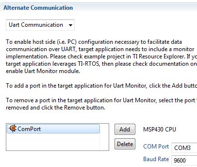
IF you haven't already, connect to your MSP430 Launchpad and take note of its enumerated COM port. You can find this information out by using the hardware manager tool inside of windows. If using Linux, you probably already know what you are doing :). Add this and the baud of 9600 as the inputs. Click the "Save" button and exit the window. What you have just done is told CCS to open a line of communication on the UART using the selected COM port at 9600 baud. The GUI Composer tool will utilize this in order to send/receive data from your program.
GUI Construction
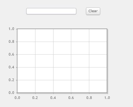
Click "View->GUI Composer" to launch the tool. If it is not there, then you haven't installed it from the CCS App Center. In the Palette tab, expand the GUI Composer item and click and drag a ValueButton onto the canvas. Do the same with the TextBox. Then expand the Instrumentation bar and insert a ScalarLineGraph. It should look like this:
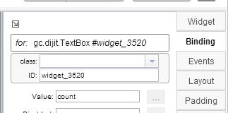
Select the textbox and then select the binding pill tab on the right-hand side. Enter count as the Value.
Now select the graph and select the Widget pill tab on the right-hand side. Under Series 0 Color, select the color to be red. Click the binding tab below it and put in count as the Value 0.
Highlight the button and click on its widget tab. Make its label = "Clear" and the Value = 0. Go to the binding tab and place count as the value. If you don't see a value row, it means you selected a regular button from the palette and not a ValueButton.
The Binding inputs will update each widget with its corresponding selected variable name. We have already defined count as a 32-bit variable in our code.
Testing
Click the Save button when finished and click the green bug in the toolbar to start your debug session.
You should notice how there are now two communication instances running as shown:
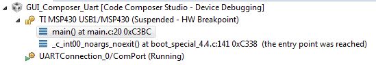
The UARTConnection will be utilized by the GUI Composer to send/receive data. The USB1 connection is used to program and debug your code as usual. Select the UARTConnection instance and then Run->Load->Load Symbols
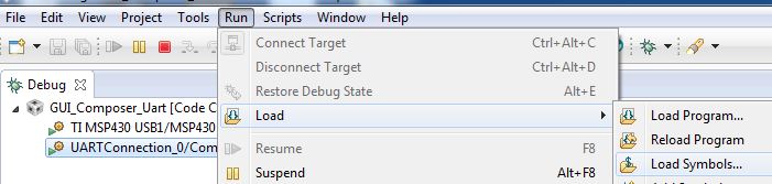
This is telling the GUI Builder where its binding variables reside in program memory so it can read/write to the correct address. The GUI will not be updated without doing this crucial step everytime you enter debug mode! I haven't found a way to automate this step. The Program File should be highlighted already as the default *.out file from your project folder. Then click the "OK" button to apply.
Next, add count to the Expressions watch window. Select the UARTConnection instance and enable the "Continuous Refresh" option as shown to see the variable changing.
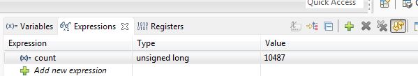
You should now see the count number incrementing! If it does not, make sure you loaded the symbols correctly. If you see an error like this:
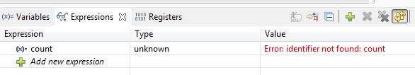
You probably have the TIMSP430 USB1 instance selected. While the target is running, the debugger prevents memory access. When you halt the target, the debugger allows memory access and the count variable will have incremented. To allow the constant refresh via the USB debugger, goto Tools->Auto Run and Launch Options and deselect the "Halt the target before any debugger access...". You should now see the variable updating in real-time in both USB1 and UART instances.
Click View->GUI Composer. Click the "Preview" button in the top-right corner. The icon looks like a little play button. You should now see your graph and input button updating as shown:
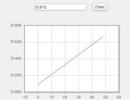
Clicking the "Clear" button will reset the count variable back to 0.
The refresh rate on default is terribly slow at around 1-2 seconds. Open up a file called app.json located in your workspace. For me, it was located here: H:\ti\workspace\.GUIComposerWS\GUI_Composer_Uart. Append this block of code to see your GUI update much faster:
{
     "serverBindName": "$refresh_interval",
     "options": {
         "dataType": "Long",
         "defaultValue" : "200"
     }
},
Save the file and you should see the affect immediately. TI recommends not to go much lower than 200ms since it may start affecting your overall program.
Deploy Stand-alone Application
Now that you have it working in your IDE, maybe its time to show a friend or show it off on a client's computer. Unfortunatily, they will have to download the GUI Composer standalone run-time environement which is a 300MB installer found here.
Navigate back to your GUI Composer tab and click the 'Export Project' button. Fill in the boxes similiar as shown:
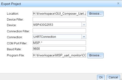
The location can be arbitrary. This just indicates where it will save the zip file of information contained in your GUI. Be sure to place the COM port filter to MSP.* and not COM* or else the standalone app won't be able to find the UART connection. Please see the offical TI docs for more information on these options here
Once you have your standalone GUI installed, extract the zip file that you just made into your ../guicomposer/webapps folder. Mine is located here: H:\ti\guicomposer\webapps The directory level is critical here. Your files should only be 1 level deep, or else clicking the exe will yield nothing. Connect your MSP430, click on the launcher.exe and your standalone should popup
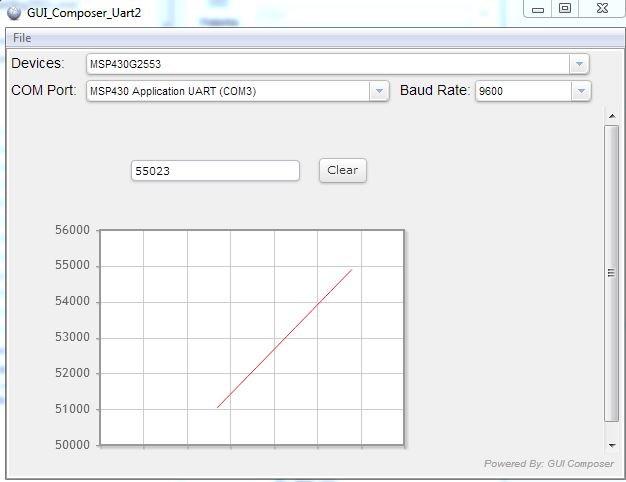
It should autoplay. You should exit any existing debugger session before launching the GUI or else it won't work properly.
Final Comments
The GUI builder can be useful for initial prototyping and showing to potential customers a gorgeous user interface. The best feature of the tool is that can act essentially as a browser by supporting javascript and html syntax. It makes it easy to anchor and align your components as well as setting up the bindings. It reminds me of visual studio's gui builder (which is a good thing!). Being able to adjust the refresh rate is also a convenient and easy to do.
The downside is that you can't just distribute a zip file with the exe and a few libraries. The client must download the 300MB middleware. Plus it only runs in windows. Having to constantly re-load the symbols during a debug session gets tedious fast.
Overall, I'd say the GUI Composer tool is a great addition from TI into its CCS IDE. It saves a bunch of time mocking up a UI in another language and framework such as Java Swing, or Qt, or Visual C#.
Comments
BBCode Tags
| BBCode | Rendering |
|---|---|
| [b]bolded text[/b] | bolded text |
| [i]italicized text[/i] | italicized text |
| [u]underlined text[/u] | underlined text |
|
Auto link already enabled. |
http://example.org |
|
Auto image already enabled. |
 |
| [code=php]<?php echo 'Hello!'; ?>[/php] | |
| [quote]quoted text[/quote] | quoted text |
|
[list] [*]Entry 1 [*]Entry 2 [/list] |
|