MSP4340 LaunchPad - Simple UART Config and Echo
Mar 27, 2016 By justin bauer
The Universal asynchronous Receive/Transmit (UART) is a vital communication protocol that is relatively easy to setup and use. It can be coded strictly in software using general purpose I/O pins, commonly referred to as bit-banged, or it can be implemented in hardware. The advantage of using the all hardware approach is that is frees the CPU to execute other code and not worry about servicing the communication. Using the hardware becomes a "must" when dealing with high enough baud. A baud of 9600 can easily be achievable in software, whilst a baud of 115200 and above becomes troublesome to accurately receive and transmit bits since there needs to be enough sampling in-between the bits. The biggest advantage of using the bit-banging method is to save on a hardware module or by using a cheaper part in production that does not have a dedicated hardware UART. I would encourage people to always utilize the hardware as much as possible and allow the CPU to process other things.
Lets go ahead and get started using code composer studio (CCS). If you haven't already installed this, please see this previous post in downloading CCS.
Create a new project at: File->New->CCS Project
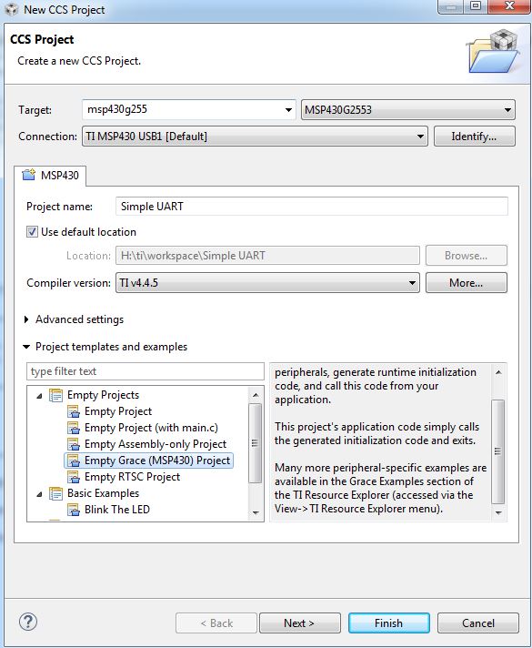
I am using the G2553 and the TI compiler. The TI compiler is free for Launchpad users up to 16KB in flash size. You should already have Grace installed which is the automatic code generator that we will be using. Click "next" and keep the default settings.
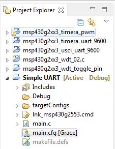
Then click main.cfg [Grace] in your project explorer
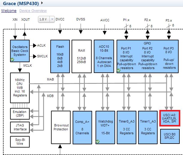
Grace provides a nice overview of the module and some sample use cases which I think is a nice touch from TI. We will be following their basic setup which is to use the UART Mode in echoing back received data.
Configuration
The Device Overview page shows what hardware modules are available according to your selected device. Unfortunately, there is no way to easy see what hardware block is in use and which are not! You have to click on each block individually to see if its enabled. The MSP430G2553 has an ADC, GPIO, UART, SPI, I2C, Comparator, and some timers. Click on the USCI UART/LIN hardware block to configure it.
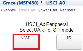
Click the checkbox Enable USCI_A0 in my Configuration. USCI means Universal Serial Communication Interface which is a fancy term to mean to indicate that each USCI shares a similar application programming interface (API) for initialization and tx/rx no matter if you are using UART,I2C,SPI,USB,etc. Once checked, you will be presented with a choice to configure the module as a UART or SPI. Select the UART choice.
Configure your module to appear as such:
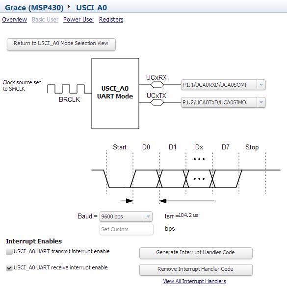
What we did is enable the RX and TX pins on the module. You are now letting the module control the pins. Applying or using these two pins, P1.1 and P1.2, in your code would have no affect since the hardware module is in control. We also configured the Baud, which is the rate of bits being sent, to 9600 bits per second. The MSP430 internally uses a series of clock dividers from your main internal clock to generate the needed rate to send and receive data at 9600 baud. Enabling the receive interrupt will allow us to echo data back to the source once we receive data.
Navigate back to your Project Explorer and double-click the src->grace->InterruptVectors_init.c file. Place this code inside the __interrupt void USCI0RX_ISR_HOOK(void) function:
/* USER CODE START (section: USCI0RX_ISR_HOOK) */

	while(!(IFG2 & UCA0TXIFG)); // Wait until TXREG is empty
	UCA0TXBUF = UCA0RXBUF; // Fill the TXREG with the RXREG...simple echo back

/* USER CODE END (section: USCI0RX_ISR_HOOK) */
This function was created by the code generator once you clicked the "Enable RX interrupt". The program counter (PC) will enter this function whenever the UART module sets the "I've received a byte" interrupt flag.
#pragma vector=USCIAB0RX_VECTOR
This tells the compiler to place the following code into the predetermined UART interrupt address. Without this #pragma, the program counter would not be able to find your interrupt service code.
while(!(IFG2 & UCA0TXIFG));
This will block execution of the CPU until the UART register is finished sending. The UCA0TXIFG will be set to a 1 whenever the UART hardware module is ready to accept data to transmit. IFG2 is an interrupt flag that indicates if the TXREG is ready for sending. Without this snippet, you would risk loading data into the TXREG when it is busy sending.
UCA0TXBUF = UCA0RXBUF;
This assigns the TXREG with whatever was received from the RXREG. The module will latch and send the data immideatly after this statement. The data is double-buffered, meaning that you can write to the TXREG during transmission and the current data should not be affected.
Any code that you add within the /* USER CODE START (section: USCI0RX_ISR_HOOK) */ is preserved between code generation. Recall that this source file is automatically generated based on your GUI configurations.
Go back and open main.c in your workplace and paste this under Grace_init();
P1DIR = BIT6; // Green LED as output
P1OUT = BIT6; // Turn ON the LED
__bis_SR_register(LPM0_bits + GIE);
The first two lines set the green LED as an output and turns it ON so we know that the program is running. The other line places the micro in a low-power state and enables interrupts. The GIE == Global Interrupt Enable flag. This line of code is not essential to get your program working as intended, but merely placed for good practice. The Grace_init() call should already enable interrupts and your main() function returning 0 will only cause the micro to forever run in a for(;;;) loop in the error handler. You can find this out for yourself by omitting that line and running the debugger and pressing the pause button during execution.
Now compile and program by pressing the build tool icon. You should see the green LED illuminate - this is good!
Connecting Hardware and Software
The Launchpad has an option to route the UART pins depending on if you are using the USCI peripheral. Since we are, you will need to rotate the jumpers 90 degrees as shown on the silkscreen.
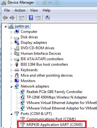
Connect the launchpad to your computer and open up your hardware manager if using windows. You should see that the MSP430 enumerates as the MSP430 Application UART. Your COM number may differ.
Connecting PC Terminal
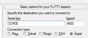
If you don't already have software to communicate via serial port, download putty. Enter the COM port number as discovered above.
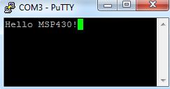
Start typing characters into the terminal and you should see the characters being echoed back!
Comments
BBCode Tags
| BBCode | Rendering |
|---|---|
| [b]bolded text[/b] | bolded text |
| [i]italicized text[/i] | italicized text |
| [u]underlined text[/u] | underlined text |
|
Auto link already enabled. |
http://example.org |
|
Auto image already enabled. |
 |
| [code=php]<?php echo 'Hello!'; ?>[/php] | |
| [quote]quoted text[/quote] | quoted text |
|
[list] [*]Entry 1 [*]Entry 2 [/list] |
|