PIC microcontroller bluetooth example with an Android phone
May 04, 2016 By justin bauer
This tutorial will cover setting up the HC-06 bluetooth device with a PIC microcontroller for Bi-directional data between the PIC and an Android phone. I will be using a PIC16F1829 in a PDIP package, which comes with the PICkit 3 Low Pin Count Demo Board or the PICkit 3 Starter Kit. You don't necessarily have to use this exact microcontroller. The code and application can be adapted for others, namely the pin mappings.
The PIC will continuously increment a 32-bit variable and print it to the bluetooth radio via its hardware UART configured at 9600 baud. Any character received through the interrupt driven RX buffer is immediately echoed back to the bluetooth device. A timer is configured to create a 500ms event that toggles an LED to show program execution. Most of the C code will be using MPLAB Code Configurator to easily setup everything.
HC-06
For general information on the HC-06 device and available commands, please see my previous Arduino post.
Interface
The module can be easily connected to the PIC via its 2 RX/TX pins on the hardware UART. The Bluetooth module adheres to the "Serial Port Profile" (SPP), which means it can communicate to a connected device just like any other normal serial port.
There is no need to modify these settings unless otherwise required. The full set of commands is detailed in this datasheet. The connection will look like the following:
| PIC16F1829 | HC-06 |
|---|---|
| TX (RC4) | RXD |
| RX (RC5) | TXD |
| PWR | PWR |
| GND | GND |
Even though the HC-06 specifies a low-voltage logic of 3.3V or less, I was still able to communicate with it just fine using a 4.8V output from the PIC. You can optionally create a voltage divider on the PIC's TX pin to step down the voltage to within 3.3V. Both will be sharing GND and PWR at around 5V.
Firmware
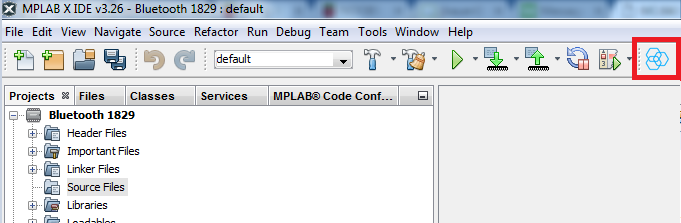
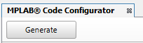
The MPLABX IDE and XC8 compiler can be freely downloaded and installed from microchip's website. The mplab code configurator (MCC) will also be used to easily setup the UART. Once installed, the code configurator icon should be displayed as shown:
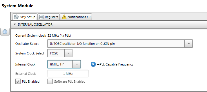
- Open up MCC and configure the system module as shown to 32MHz. This is the maximum frequency that this chip can run at. The Phase Locked Loop (PLL) must be enabled for this to happen. The Internal 8MHz is multiplied by a factor of 4 to create a somewhat stable (+/-5%) internal clock. Since we aren't doing any critical timing in this demo, this percentage of error is acceptable:
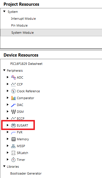
- Open the 'EUSART' module
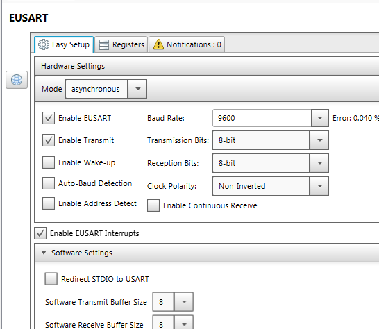
- Enable interrupts and configure it as such. Note that we will be using the receive interrupt which will instruct our code to echo the character back without needing to poll the UART module if it received anything yet.
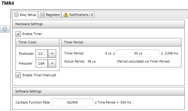
- I always place an LED toggle routine into my code so that I can visually tell when my program is running. We will be using a timer (TMR4) to create a periodic interrupt for us to toggle an indicator LED. Expand the "Timer" module and double click on "TMR4". Setup the module as such to create an approximate 500ms interrupt.
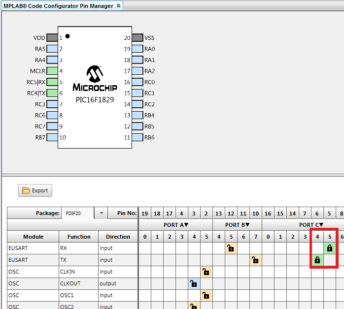
- Expand the right-hand side of the IDE to see the MCC Pin Manager. It is here when you can make your route your UART hardware module to an associated pin. Make the following selections. EUSART RX = RC5 and EUSART TX = RC4:
- Click the "Generate" button
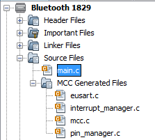
- The code generator should have generated the following files in your workspace:
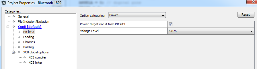
- Allow the PICkit3 to power the board. Right-click the project and navigate to "properties". Click the "PICkit 3" and set the "Option Categories" dropdown box to "power" and check the box and select 4.875V. The reason not to use 5V is because I've noticed that sometimes the PICkit is unable to deliver the 5V under a moderate load and will error out
- Click the download button after connecting your pickit and you are ready to test!

- You should see an LED periodically turn ON and OFF if the firmware is working. The red LED on the HC-06 should also be blinking at a rapid rate
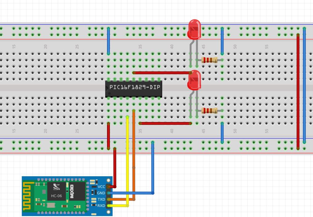
Schematic
I am using the low-pin-count demo board. I am also using 4 breadboard wires to connect the module to the board. You can also just breadboard the PIC and the bluetooth module to save cost.
Android Testing
- Download an app called BlueTerm2 from the play store.
- Once installed, open up the app click the "Connect device" button.
- You should see the Bluetooth device come up called "hc-06" or "mcuhq.com".
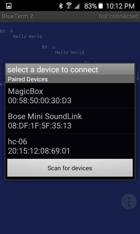
- Connect to the device to see a continuous number being printed to the screen.
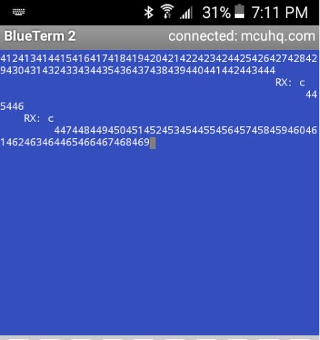
- Touch a key to send a character and see it echoed back. Pressing the
ccharacter will toggle another LED
Software Explanation
The code on the PIC16F1829 is coded in the "C" programming language and compiles with the C99 standard. It was compiled using Microchip Technologies MPLABX integrated development environment (IDE) XC8 compiler for 8-bit microcontrollers. The hardware UART module is used to communicate with the HC-06 device. The code configurator was used to easily setup the configuration bits and hardware.
Main Routine - Includes and Prototypes
The main.c file includes the auto-generated configuration files (mcc.h) and the PIC hardware system files as well as a standard C library in order to use the printf function. Two static functions are also placed at the top so that the rest of the program can call them. The putch and uartWrite functions are for sending data to the bluetooth module. The timer4ISR() is a function that will be called when the auto-generated timer4 interrupt occurs. I prefer to use function pointers so that I can keep all of my application code separate from the auto-generated code. You can always paste your code into the auto-generated interrupt handler directly within the /*Enter your code here*/ blocks. A global tmp variable is incremented every time your LED toggles. This is just to demonstrate program functionality.
#include "mcc_generated_files/mcc.h"
#include <stdio.h>  // used for printf
#include <xc.h>     // register mappings
void putch(char d); // the 'printf' function uses this for its printing.
                    // we are going to override it so it prints to the UART
static void uartWrite(char d); // function for printing one character at a time
void timer4ISR(); // function callback from TMR4 interrupt routine
static uint32_t tmp; // global temp variable that will be sent to
Main Routine - Pin Setup
The System_Initialize will call the auto-generated MCC hardware setup. Then the code will enable interrupts for the hardware UART to receive data. A single LED is toggled every 500ms from the TIMER4 interrupt to show that the program is running. Another LED will also be toggled if the letter c character is received. In order for this to happen, the RC0 pin where this LED is connected must be configured to be a digital, output. RC3 is also configured the same as RC0. You could have optionally configured this inside of MCC as well.
Take note of the code passing our timer4ISR() function into the auto-generated API SetInterruptHandler. This causes any TMR4 interrupts to call our timer4ISR function where we toggle and LED and increment our tmp variable.
void main(void)
{
    // initialize the device
    SYSTEM_Initialize();
    // Enable the Global Interrupts
    INTERRUPT_GlobalInterruptEnable();
    // Enable the Peripheral Interrupts
    INTERRUPT_PeripheralInterruptEnable();
    // Create a call-back to our own implementation of a timer4 interrupt
    TMR4_SetInterruptHandler(timer4ISR);

    // pin configuration for the two LEDs
    ANSELCbits.ANSC0 = 0; // digital pin
    ANSELCbits.ANSC3 = 0; // digital pin
    TRISCbits.TRISC0 = 0; // output
    TRISCbits.TRISC3 = 0; // output
    WPUCbits.WPUC0 = 0; // disable weak pull-up
    WPUCbits.WPUC3 = 0; // disable weak pull-up

     __delay_ms(2000); // delay for HC-06 initialization
    printf("AT+NAMEmcuhq.com");
    __delay_ms(4000); // wait for setting to take effect
For fun, the name of the Bluetooth device was changed. You can place your own text in place of the mcuhq.com
Main Loop
The main loop is created by making a single while(1), which will run forever until power is lost. The __delay_ms() macro is used for necessary delays. It is defined inside of the XC8 compiler.
The RX buffer will be checked for incoming data next by reading the variable 'eusartRxCount' which is a global variable defined in the auto-generated eusart code. This variable is incremented anytime the RX interrupt occurs. Simply check this value for non-zero to see if any data has been received. If there is data, the code will read it via the external function EUSART_Read() which will return the first character received.
while (1)
    {
        if(eusartRxCount != 0){
            char rxChar = EUSART_Read(); // check to see if received anything on the UART
            printf("\nRX: %c\n", rxChar); // if yes, echo it back
            if(rxChar == '1') // if we got a number '1', toggle an LED
                LATCbits.LATC3 ^= 1; // toggle this
        }
    }
Configuration Bits
The micro will be using the internal RC oscillator at 8MHz with the 4x Phase-Locked-Loop (PLL) to increase it to 32MHz. The watchdog timer was configured to be OFF. The master clear functionality was also turned OFF so as to not accidently resetting the micro on its RA1 input. Here are the configuration settings:
#pragma config FOSC = INTOSC    // Oscillator Selection->INTOSC oscillator: I/O function on CLKIN pin
#pragma config WDTE = OFF    // Watchdog Timer Enable->WDT disabled
#pragma config PWRTE = OFF    // Power-up Timer Enable->PWRT disabled
#pragma config MCLRE = ON    // MCLR Pin Function Select->MCLR/VPP pin function is MCLR
#pragma config CP = OFF    // Flash Program Memory Code Protection->Program memory code protection is disabled
#pragma config CPD = OFF    // Data Memory Code Protection->Data memory code protection is disabled
#pragma config BOREN = ON    // Brown-out Reset Enable->Brown-out Reset enabled
#pragma config CLKOUTEN = OFF    // Clock Out Enable->CLKOUT function is disabled. I/O or oscillator function on the CLKOUT pin
#pragma config IESO = ON    // Internal/External Switchover->Internal/External Switchover mode is enabled
#pragma config FCMEN = ON    // Fail-Safe Clock Monitor Enable->Fail-Safe Clock Monitor is enabled

// CONFIG2
#pragma config WRT = OFF    // Flash Memory Self-Write Protection->Write protection off
#pragma config PLLEN = ON    // PLL Enable->4x PLL enabled
#pragma config STVREN = ON    // Stack Overflow/Underflow Reset Enable->Stack Overflow or Underflow will cause a Reset
#pragma config BORV = LO    // Brown-out Reset Voltage Selection->Brown-out Reset Voltage (Vbor), low trip point selected.
#pragma config LVP = OFF    // Low-Voltage Programming Enable->High-voltage on MCLR/VPP must be used for programming
Hardware UART
The UART was configured in its asynchronous mode with the following settings:
- 9600 Baud rate
- 8-bit transmission, 1 stop/start bit
- 8 byte RX buffer size
Transmit Routine
The main code uses the printf function to format and then send out the data via the hardware UART. This is achieved by implementing the putch method that the printf function uses to print the characters. The putch method accepts an 8-bit character type and sends it to the uartWrite method which first waits for the UART module to be ready before sending another byte via the TXREG.
void putch(char d){
    uartWrite(d);
}

static void uartWrite(char txData){
    while(0 == PIR1bits.TXIF); // wait for current byte to finish sending
    TXREG = txData;    // Write the data byte to the USART.
}
Receive Routine
The micro uses interrupts to handle the receiving of data from the Bluetooth module. Here is the interrupt manager which will be used whenever a full 8-bit character is received.
void interrupt INTERRUPT_InterruptManager (void)
{
   // interrupt handler
if(PIE1bits.RCIE == 1 && PIR1bits.RCIF == 1)
    {
        EUSART_Receive_ISR();
    }
    else
    {
        //Unhandled Interrupt
    }
}
It then calls an auto-generated RX routine that saves the data in an 8-byte First-in-First-Out (FIFO) buffer. If the buffer receives its last byte without being read, it simply overwrites the first byte again.
void EUSART_Receive_ISR(void)
{
    if(1 == RCSTAbits.OERR)
    {
        // EUSART error - restart

        RCSTAbits.CREN = 0;
        RCSTAbits.CREN = 1;
    }

    // buffer overruns are ignored
    eusartRxBuffer[eusartRxHead++] = RCREG;
    if(sizeof(eusartRxBuffer) <= eusartRxHead)
    {
        eusartRxHead = 0;
    }
    eusartRxCount++;
}
Timer interrupt
Expanding the Demo
Toggling I/O such as an LED, Relay, Motor, etc can be added to the code. You can now control functionality from your phone! You can easily map single characters to actions made on the microcontroller
if(rxChar == 't'){ // did we get anything?
        // Turn on motor
    }
else if(rxChar == 'a'){
    // Turn on LED and open garage door
}
//...
Displaying the received text onto an LCD is an extremely easy task. Please see this post for more information on connecting an HD47780 LCD to the PIC. You can also create your own Android Application to communicate with this same code. Please see this post for more information.
Please leave a comment if you have any problems or suggestions.
Comments
BBCode Tags
| BBCode | Rendering |
|---|---|
| [b]bolded text[/b] | bolded text |
| [i]italicized text[/i] | italicized text |
| [u]underlined text[/u] | underlined text |
|
Auto link already enabled. |
http://example.org |
|
Auto image already enabled. |
 |
| [code=php]<?php echo 'Hello!'; ?>[/php] | |
| [quote]quoted text[/quote] | quoted text |
|
[list] [*]Entry 1 [*]Entry 2 [/list] |
|