HD44780 LCD Driver for a PIC
Apr 09, 2016 By justin bauer
The post will utilize the popular Hitachi HD44780 16x2 Character LCD (sometimes mispelled HD47780) to print simple messages from an 8-bit PIC. I will be using the PIC16F1829 to write to the LCD in 4-bit mode (only 4 pins). The PIC16F1829 comes with the PICkit 3 Low Pin Count Demo Board or the PICkit 3 Starter Kit. Microchip's starter kit hardware and demo tools can be expensive, so you don't have to necessarily buy the whole package if you just want the micro. You can easily get this tutorial working by buying the micro on digikey and connecting to it via a breadboard.
There are a lot of LCD variants that you can purchase that contain the HD44780 driver. I ordered mine from Amazon for $10. You should be able to get one for around that same price.
You can download the universal PIC driver on github here: https://github.com/mcuhq/hd44780-driver-for-PIC
HD44780 Driver Features
Here are the callable features of the driver:
- Any 8-bit PIC micro will work
- 8-bit or 4-bit operation
- Two-line or One-line mode
- 16 character and 8 character support
- Blinking and Cursor optional ON/OFF
- Variable positioning on LCD
- Clear Screen
PIC16F1829 Code
I am going to be using the MPLABX IDE and XC8 compiler which are free to download and install. I won't be using the microchip code generator (MCC) in this tutorial since it should be a fairly straight forward design.
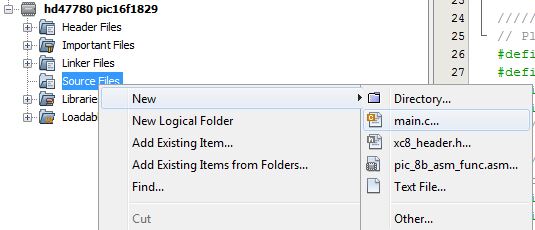
Create a new project inside of MPLABX and identify the micro as a PIC16F1829. I named my project "hd44780 pic16f1829". Right-click the "Source Files" folder and create a new main.c file.
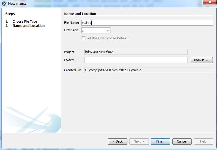
Name it main.c
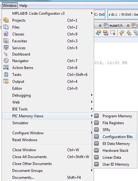
We first need to adjust the "fuses" or rather "configuration bits" which setup important information such as clock selection, watchdog timer, master clear, etc. Navigate to "Window->PIC Memory Views->Configuration Bits".
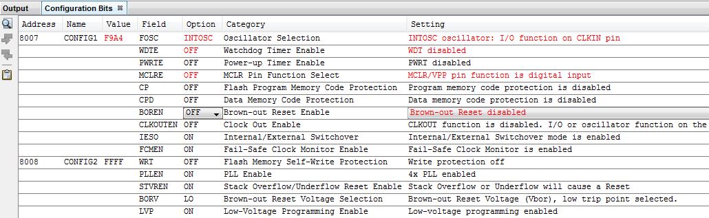
Make the following config bits as follows
| Field | Option | |
|---|---|---|
FOSC |
INTOSC |
We will be using the internal oscillator |
WDTE |
OFF |
Turn OFF the watchdog timer that would otherwise cause a reset if not cleared in our software |
MCLRE |
OFF |
Disable the Master Clear from happening on RA4. Leaving this enabled may cause the PIC to reset |
BOREN |
OFF |
Because we will be powering the PIC and LCD via the PICkit 3, it may drop the voltage a bit which could cause a reset |
Now click the "Generate Source Code to Output" button

This will copy the config bits to your main.c
main.c
Code your main.c file as such:
#include <xc.h>
// #pragma config statements should precede project file includes.
// Use project enums instead of #define for ON and OFF.
// CONFIG1
#pragma config FOSC = INTOSC // Oscillator Selection Bits (INTOSC oscillator: I/O function on CLKIN pin)
#pragma config WDTE = OFF // Watchdog Timer Enable (WDT disabled)
#pragma config PWRTE = OFF // Power-up Timer Enable (PWRT disabled)
#pragma config MCLRE = ON // MCLR Pin Function Select (MCLR/VPP pin function is MCLR)
#pragma config CP = OFF // Flash Program Memory Code Protection (Program memory code protection is disabled)
#pragma config BOREN = ON // Brown-out Reset Enable (Brown-out Reset enabled)
#pragma config CLKOUTEN = OFF // Clock Out Enable (CLKOUT function is disabled. I/O or oscillator function on the CLKOUT pin)
#pragma config IESO = ON // Internal/External Switchover Mode (Internal/External Switchover Mode is enabled)
#pragma config FCMEN = ON // Fail-Safe Clock Monitor Enable (Fail-Safe Clock Monitor is enabled)
// CONFIG2
#pragma config WRT = OFF // Flash Memory Self-Write Protection (Write protection off)
#pragma config PPS1WAY = ON // Peripheral Pin Select one-way control (The PPSLOCK bit cannot be cleared once it is set by software)
#pragma config ZCDDIS = ON // Zero-cross detect disable (Zero-cross detect circuit is disabled at POR)
#pragma config PLLEN = ON // Phase Lock Loop enable (4x PLL is always enabled)
#pragma config STVREN = ON // Stack Overflow/Underflow Reset Enable (Stack Overflow or Underflow will cause a Reset)
#pragma config BORV = LO // Brown-out Reset Voltage Selection (Brown-out Reset Voltage (Vbor), low trip point selected.)
#pragma config LPBOR = OFF // Low-Power Brown Out Reset (Low-Power BOR is disabled)
#pragma config LVP = ON // Low-Voltage Programming Enable (Low-voltage programming enabled)
#include "lcd.h"
#include <stdio.h>
#include <string.h>
void main(void) {
// 32MHz setup
OSCCONbits.SPLLEN = 1; // enable PLL
OSCCONbits.IRCF = 0b1110; // 8MHz (32MHz when PLL enabled)
// Pin init
TRISC = TRISB = 0; // Set all pins as outputs
ANSELC = ANSELB = 0; // Set pins as digital
WPUC = WPUB = 0; // Disable the weak internal pull-ups
LATB = LATC = 0; // Start with all pins driven LOW
initLCD();
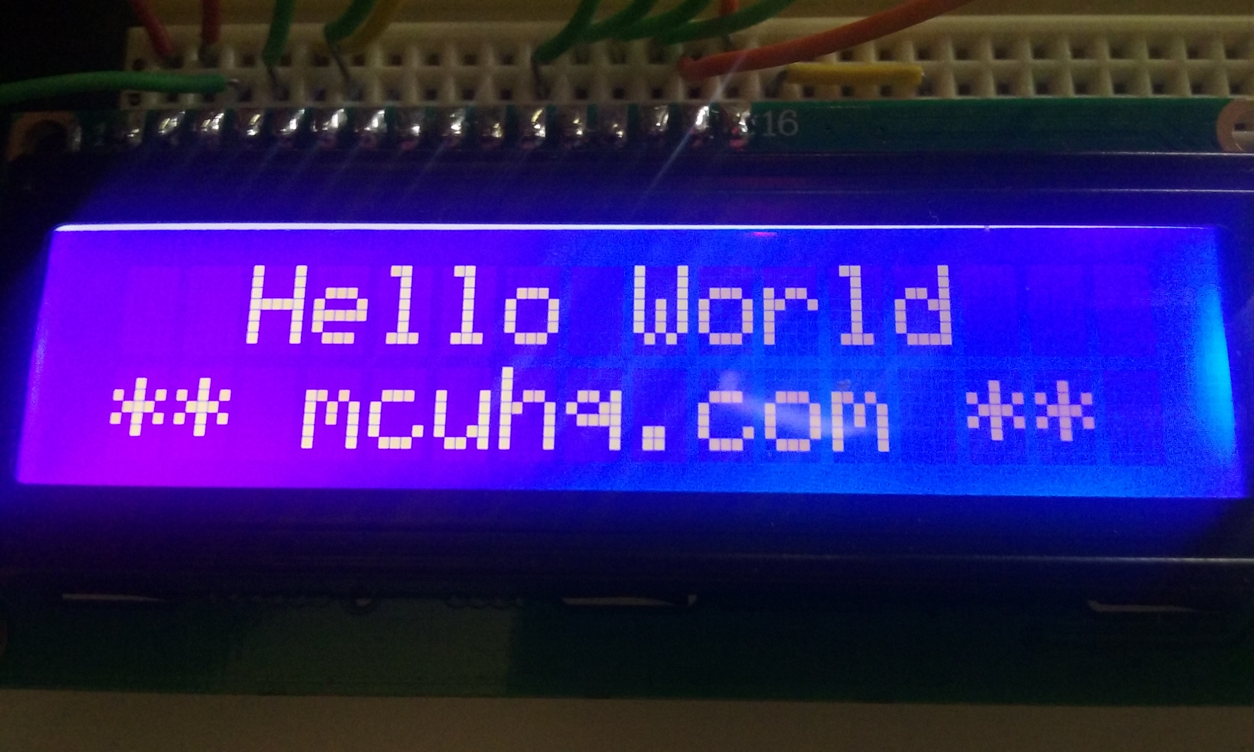
gotoLCD(FIRST_LINE);
printf(" Hello World");
gotoLCD(SECOND_LINE);
printf("** mcuhq.com **");
//gotoLCD(SECOND_LINE);
while (1) {
LATCbits.LATC0 ^= 1;
__delay_ms(1000);
}
}
void putch(char c) {
lcdWrite(c, DATA);
}
Do not worry about the errors you see that are highlighted in the IDE since we have not added the LCD drive files yet.
    // 32MHz setup
    OSCCONbits.SPLLEN = 1; // enable PLL
    OSCCONbits.IRCF = 0b1110; // 8MHz (32MHz when PLL enabled)
The OSCCON register sets the internal oscillator speed and configuration. Notice how we are using the OSCCON structure with the . syntax. The xc.h header file that you included contains these definitions. You can optionally just write directly to the register using an 8-bit hex or 8-bit binary value. I like using the bit fields since it is more explicit and easier to read. We will be maximizing the processor speed to 32MHz. We first enable the PLL (Phase-Locked-Loop) that multiplies the 8MHz by 4 to get 32MHz. The maximum speed of Microchip's 8-bit product line is 48MHz. This is mandatory for any USB powered PICs such as the PIC16F1455.
    // Pin init
    TRISC = TRISB = 0;   // Set all pins as outputs
    ANSELC = ANSELB = 0; // Set pins as digital
    WPUC = WPUB = 0; // Disable the weak internal pull-ups
    LATB = LATC = 0; // Start with all pins driven LOW
I'll be using pins on PORTB and PORTC. The TRISX registers set the direction. Think 0 as Output and 1 and Input. The ANSELX registers define whether the level will be digital or analog. We will be using the pins in digital mode. The WPUX register can enable or disable the internal pull-up resistors. Often times these are useful to save on external resistors for button switches or communication purposes. Lets disable them for now. The LATX is what you want to write to in order to drive the pin LOW or HIGH.
    initLCD();
    gotoLCD(FIRST_LINE);
    printf("  Hello World");
    gotoLCD(SECOND_LINE);
    printf("** mcuhq.com **");
These are the LCD API functions. They are defined in lcd.h. We are simply printing two strings to the LCD. These will be talked about next.
while (1) {
        LATCbits.LATC0 ^= 1;
        __delay_ms(1000);
    }
This blinks an optional LED to indicate that the program is running. The ^=1 toggles the pin.
void putch(char c) {
    lcdWrite(c, DATA);
}
I will be using the widely used printf function to format and write to the LCD. We are overriding the default behavior of printf and telling it to print to the LCD instead of the debug console. Please note that by using printf, your code will execute much slower versus just simply creating a function to print a string. The printf functionality is easy to understand and much more flexible, which is why I'm using it here. Your application may want to remove this if you are space and execution speed limited. The lcd API contains another function that you can use instead if this is the case.
LCD API
Create two new files called lcd.c and lcd.h by right-clicking your "source files" and "header Files" folders.
lcd.h
Paste the following into lcd.c
#include "lcd.h"


#include <xc.h>
#include <stdint.h>

////////////////////////////////////////////////////////
// Don't touch these values
#define _4BIT 0
#define _8BIT 1
#define _ON 1
#define _OFF 0
#define _ONE_LINE 0
#define _TWO_LINES 1
////////////////////////////////////////////////////////

////////////////////////////////////////////////////////
// Place your LCD customizations here
#define MODE _4BIT // Valid options are _4BIT or _8BIT
#define CURSOR _OFF // Valid options are ON or OFF
#define BLINK _OFF // Valid option are ON or OFF
#define NUMLINES _TWO_LINES // Valid options are ONE_LINE or TWO_LINES
////////////////////////////////////////////////////////

////////////////////////////////////////////////////////
//Replace the following pin definitions with your hardware
#define RS LATCbits.LATC6
#define EN LATCbits.LATC7
// Required for 8-bit
#define D0 LATCbits.LATC0
#define D1 LATCbits.LATC1
#define D2 LATCbits.LATC2
#define D3 LATCbits.LATC3
// Required for 4-bit
#define D4 LATBbits.LATB4
#define D5 LATBbits.LATB5
#define D6 LATBbits.LATB6
#define D7 LATBbits.LATB7
/////////////////////////////////////////////////////////


static void lcdNibble(uint8_t nibble);
static void lcdByte(uint8_t byte);

/**
 *  Initialize LCD according to page 45, FIGURE 24 on the Hitachi datasheet
 */
extern void initLCD(){
    RS = 0;
    EN = 0;

    __delay_ms(40); // wait 10ms for lcd internal initialization

#if(MODE == _4BIT)
    // First send the HIGH nibble of the Function set
    lcdNibble(0b0011); // Function set - Interface defaults to 8-bit mode
    __delay_ms(5);
    lcdNibble(0b0011);// Function set - Interface defaults to 8-bit mode
    __delay_ms(5);
    lcdNibble(0b0011);// Function set - Interface defaults to 8-bit mode
    __delay_ms(5);
    lcdNibble(0b0010); // Now set the interface to 4-bit mode
    __delay_ms(5);
#elif(MODE == _8BIT)
    lcdWrite(0b00110000);
    __delay_ms(5);
    lcdWrite(0b00110000);
    __delay_ms(5);
    lcdWrite(0b00110000);
    __delay_ms(5);s
#else
#error Bit Mode not defined
#endif
    //volatile uint8_t test = ((0b1100) | (CURSOR << 1) | (BLINK << 0));
    lcdWrite(((0b0010 << 4) | (NUMLINES << 3)), COMMAND); // 0x28 = 4-bit, 2-line, 5x8 font size
    __delay_ms(5);
    lcdWrite(((0b1100) | (CURSOR << 1) | (BLINK << 0)), COMMAND); // 0x0C = Turn ON display, no cursor, no blinking
    __delay_ms(8);
    clearLCD(); // Clear the screen
    __delay_ms(5);
    lcdWrite(0x06, COMMAND); // Move from left-to-right, no shifting
    __delay_ms(5);
    clearLCD();

    RS = 1;

}

/**
 * Sets the cursor to the beginning of first or second line
 *
 * @param pos
 */
extern void gotoLCD(LCD_POSITION pos)
 {
    RS = 0;

     if(pos == FIRST_LINE)
        lcdWrite(0x80, COMMAND);
     else
       lcdWrite(0x80 + 0x40, COMMAND);
 }

/**
 * Clears the LCD
 */
extern void clearLCD(){
    lcdWrite(0x01, COMMAND);
    __delay_ms(2);
}

/**
 * Write a byte to the LCD
 * @param byte 8-bit data
 * @param type RS pin depends on data type if command or not
 */
extern void lcdWrite(uint8_t byte, LCD_REGISTER_TYPE type){
    if(type == COMMAND) // check expected data type
        RS = 0; // sending special commands (see hd44780 datasheet)
    else
        RS = 1; // assume actual data

    __delay_us(100);
#if(MODE == _4BIT)
    lcdNibble(byte >> 4); // send higher 4-bits
    lcdNibble(byte & 0x0F); // send lower 4-bits
#else
    lcdByte(byte);
#endif
}

/**
 * Prints to the LCD without needing to use printf
 * @param t string of characters to send to lcd
 */
extern void lcdPrint(char *t){
    while(*t != '\0'){
        lcdWrite(*t++, DATA);
    }
}

/**
 * Used for 4-bit mode operation
 * @param nibble 4 bits of data to send to lcd
 */
static void lcdNibble(uint8_t nibble){
    D4 = (nibble & 0x01) ? 1 : 0;
    D5 = (nibble & 0x02) ? 1 : 0;
    D6 = (nibble & 0x04) ? 1 : 0;
    D7 = (nibble & 0x08) ? 1 : 0;

    // Now strobe
    EN = 1;
    __delay_us(100);
    EN = 0;
    __delay_us(100);
}

/**
 * Used for 8-bit mode operation
 * @param byte
 */
static void lcdByte(uint8_t byte){
    D0 = (byte & 0x01) ? 1 : 0;
    D1 = (byte & 0x02) ? 1 : 0;
    D2 = (byte & 0x04) ? 1 : 0;
    D3 = (byte & 0x08) ? 1 : 0;
    D4 = (byte & 0x10) ? 1 : 0;
    D5 = (byte & 0x20) ? 1 : 0;
    D6 = (byte & 0x40) ? 1 : 0;
    D7 = (byte & 0x80) ? 1 : 0;

    // Now strobe
    EN = 1;
    __delay_us(100);
    EN = 0;
    __delay_us(100);
}
////////////////////////////////////////////////////////
// Don't touch these values
#define _4BIT 0
#define _8BIT 1
#define _ON 1
#define _OFF 0
#define _ONE_LINE 0
#define _TWO_LINES 1
////////////////////////////////////////////////////////
These are used to help determine the LCD configuration. Don't Modify these. I place an underscore before each of these so they won't interfere with any other settings in your code or the default XC8 defines.
////////////////////////////////////////////////////////
// Place your LCD customizations here
#define MODE _4BIT // Valid options are _4BIT or _8BIT
#define CURSOR _OFF // Valid options are ON or OFF
#define BLINK _OFF // Valid option are ON or OFF
#define NUMLINES _TWO_LINES // Valid options are ONE_LINE or TWO_LINES
////////////////////////////////////////////////////////
Here is where you can define your LCD with the allowable options.
////////////////////////////////////////////////////////
//Replace the following pin definitions with your hardware
#define RS LATCbits.LATC6
#define EN LATCbits.LATC7
// Required for 8-bit
#define D0 LATCbits.LATC0
#define D1 LATCbits.LATC1
#define D2 LATCbits.LATC2
#define D3 LATCbits.LATC3
// Required for 4-bit
#define D4 LATBbits.LATB4
#define D5 LATBbits.LATB5
#define D6 LATBbits.LATB6
#define D7 LATBbits.LATB7
/////////////////////////////////////////////////////////
Here is where you need to specify what pin is connected to what pin on the LCD. I am using the Low Pin Count Demo Board, so my pin definitions may look different than yours. As you can see, I am using only pins on PORTB and PORTC. Make sure that whatever pins you used are initialized correctly as seen in main.c. If you are not using the LCD in its 8-bit mode, you can simply place a dummy pin location for D0-D3.
static void lcdNibble(uint8_t nibble);
static void lcdByte(uint8_t byte);
It is good practice to encapsulate functions inside of a single file so as to prevent misuse and limit its scope. These two functions should only be used inside of the LCD source file.
extern void initLCD(){
    RS = 0;
    EN = 0;

    __delay_ms(40); // wait 10ms for lcd internal initialization
The RS pin is used to tell the LCD whether the data being sent to it should be interpreted as a command or regular char data. The EN pin is used a "strobe" to validate the data. This is toggled at the end of every data byte sent.
#if(MODE == _4BIT)
    // First send the HIGH nibble of the Function set
    lcdNibble(0b0011); // Function set - Interface defaults to 8-bit mode
    __delay_ms(5);
    lcdNibble(0b0011);// Function set - Interface defaults to 8-bit mode
    __delay_ms(5);
    lcdNibble(0b0011);// Function set - Interface defaults to 8-bit mode
    __delay_ms(5);
    lcdNibble(0b0010); // Now set the interface to 4-bit mode
    __delay_ms(5);
#elif(MODE == _8BIT)
The initialization must be followed EXACTLY as indicated on the datasheet, specifically Figure 24 as shown
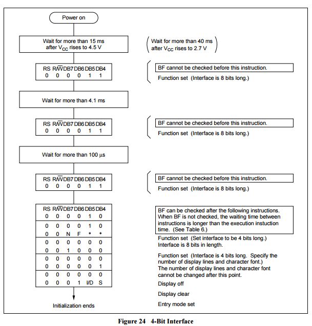
The code above follows this routine to put it into 4-bit mode.
#elif(MODE == _8BIT)
    lcdWrite(0b00110000);
    __delay_ms(5);
    lcdWrite(0b00110000);
    __delay_ms(5);
    lcdWrite(0b00110000);
    __delay_ms(5);s
#else
#error Bit Mode not defined
#endif
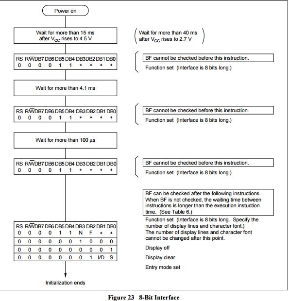
This code follows this format:
   //volatile uint8_t test = ((0b1100) | (CURSOR << 1) | (BLINK << 0));
    lcdWrite(((0b0010 << 4) | (NUMLINES << 3)), COMMAND); // 0x28 = 4-bit, 2-line, 5x8 font size
    __delay_ms(5);
    lcdWrite(((0b1100) | (CURSOR << 1) | (BLINK << 0)), COMMAND); // 0x0C = Turn ON display, no cursor, no blinking
    __delay_ms(8);
    clearLCD(); // Clear the screen
    __delay_ms(5);
    lcdWrite(0x06, COMMAND); // Move from left-to-right, no shifting
    __delay_ms(5);
    clearLCD();

    RS = 1;
This follows the 4-bit and 8-bit initialization routines. The #defines above are used here to init the LCD in its proper method. Please see the hitachi 44780 datasheet for more information regarding bit placement and defintion.
extern void gotoLCD(LCD_POSITION pos)
 {
    RS = 0;

     if(pos == FIRST_LINE)
        lcdWrite(0x80, COMMAND);
     else
       lcdWrite(0x80 + 0x40, COMMAND);
 }
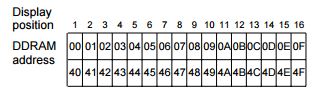
The position can be changed by calling this function with an LCD_POSITION enumeration. The enumeration is defined in the lcd.h header file. This can either be FIRST_LINE or SECOND_LINE. The 0x80 is the command byte and address 0x00 and 0x40 determine the cursor placement as seen in the datasheet here:
extern void clearLCD(){
    lcdWrite(0x01, COMMAND);
    __delay_ms(2);
}
Simply clears the lcd. Please note the delay time.
extern void lcdWrite(uint8_t byte, LCD_REGISTER_TYPE type){
    if(type == COMMAND) // check expected data type
        RS = 0; // sending special commands (see hd44780 datasheet)
    else
        RS = 1; // assume actual data

    __delay_us(100);
#if(MODE == _4BIT)
    lcdNibble(byte >> 4); // send higher 4-bits
    lcdNibble(byte & 0x0F); // send lower 4-bits
#else
    lcdByte(byte);
#endif
}
This function sends 8-bit data to the LCD. The RS pin is set or cleared Depending on whether or not the data should be interpreted as an lcd command or regular character data. If using 4-bit mode, two nibbles (4-bit data chunks) are sent at a time. 8-bit data mode does not have this restriction can can send the full 8-bits at once.
extern void lcdPrint(char *t){
    while(*t != '\0'){
        lcdWrite(*t++, DATA);
    }
}
The user can optionally use this lean and fast method of printing a string to the LCD instead of using printf
static void lcdNibble(uint8_t nibble){
    D4 = (nibble & 0x01) ? 1 : 0;
    D5 = (nibble & 0x02) ? 1 : 0;
    D6 = (nibble & 0x04) ? 1 : 0;
    D7 = (nibble & 0x08) ? 1 : 0;

    // Now strobe
    EN = 1;
    __delay_us(100);
    EN = 0;
    __delay_us(100);
}
Used in 4-bit mode, this performs ternary operations in communication.
static void lcdByte(uint8_t byte){
    D0 = (byte & 0x01) ? 1 : 0;
    D1 = (byte & 0x02) ? 1 : 0;
    D2 = (byte & 0x04) ? 1 : 0;
    D3 = (byte & 0x08) ? 1 : 0;
    D4 = (byte & 0x10) ? 1 : 0;
    D5 = (byte & 0x20) ? 1 : 0;
    D6 = (byte & 0x40) ? 1 : 0;
    D7 = (byte & 0x80) ? 1 : 0;

    // Now strobe
    EN = 1;
    __delay_us(100);
    EN = 0;
    __delay_us(100);
}
Same as the 4-bit, except expand to the full 8-bit wide communication.
lcd.h
Paste the following into your lcd.h file
// This is a guard condition so that contents of this file are not included
// more than once.
#ifndef __LCD_H_
#define	__LCD_H_

#include <xc.h> // include processor files - each processor file is guarded.
#include <stdint.h>
#define _XTAL_FREQ 32000000

typedef enum{
    FIRST_LINE,
    SECOND_LINE,
}LCD_POSITION;

typedef enum{
    COMMAND,
    DATA,
}LCD_REGISTER_TYPE;

extern void initLCD();
extern void clearLCD();
extern void lcdWrite(uint8_t byte, LCD_REGISTER_TYPE type);
extern void gotoLCD(LCD_POSITION pos);
extern void lcdPrint(char *t);

#endif
#include <stdint.h>
You should have noticed by now that I used the standard definition types such as uint8_t. This guarantees to the programer that the data-type is going to be 8-bits wide. Data types differ between architectures - most notably the int could be 16-bits or 32-bits. Use these data types for best practice.
#define _XTAL_FREQ 32000000
This needs to be defined in order for the __delay_ms(x) macros to work. These are defined in the XC8 compiler and are generated during compilation, so it needs to know how many nops, or "no operations" and such to place in order to achieve the desired delay time.
typedef enum{
    FIRST_LINE,
    SECOND_LINE,
}LCD_POSITION;

typedef enum{
    COMMAND,
    DATA,
}LCD_REGISTER_TYPE;
This is an enum which is an encapsulated version of #define. I used this to enforce parameters in the lcd API.
extern void initLCD();
extern void clearLCD();
extern void lcdWrite(uint8_t byte, LCD_REGISTER_TYPE type);
extern void gotoLCD(LCD_POSITION pos);
extern void lcdPrint(char *t);
All of these are extern which make them callable by the other souce files in your project, like main.c.
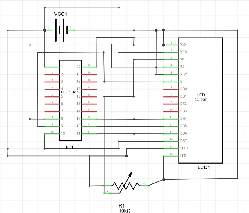
Hardware
There are 6 connections total that we will be using to communicate with the LCD. 4 for data and 2 for general communication. The connections are as follows
| LCD | Function | PIC Pin |
|---|---|---|
| 1 | GND | GND |
| 2 | PWR | +5V |
| 3 | Contrast | POT |
| 4 | RS | RC6 |
| 5 | RW | GND |
| 6 | EN | RC7 |
| 7 | Data0 | - |
| 8 | Data1 | - |
| 9 | Data2 | - |
| 10 | Data3 | - |
| 11 | Data4 | RB4 |
| 12 | Data5 | RB5 |
| 13 | Data6 | RB6 |
| 14 | Data7 | RB7 |
| 15 | Backlight+ | +5V |
| 16 | Backlight- | GND |
Here is a breadboard mockup. The POT is used to change the lcd contrast. The lcd has its backlight permanently connected to +5V and GND. Please note that this is using 5V!
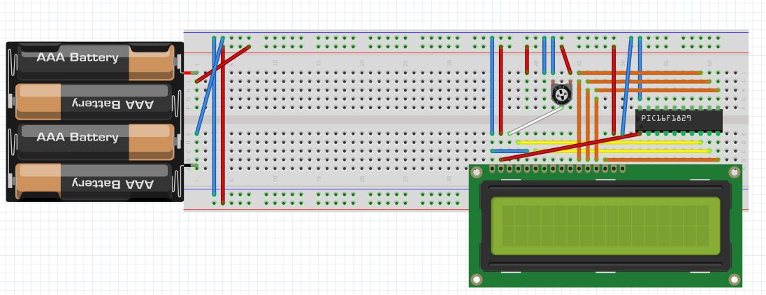
And here the schematic. This is my first time using fritzing to create a schematic. It is certainly clunky and hard to make professional looking schematics. I'm not sure if I will continue using it for larger projects
Testing
Click the build button and ensure it builds correctly. Be sure to change your pin definitions accordingly if you are using a different micro or hardware.
I like to use the programmer to source the power without the needing of additional batteries or power supply. Right-click the project and navigate to “propertiesâ€. Click the “PICkit 3†and set the “Option Categories†dropdown box to “power†and check the box and select 4.875V. The reason not to use 5V is because I’ve noticed that sometimes the PICkit is unable to deliver the 5V under a moderate load and will error out.
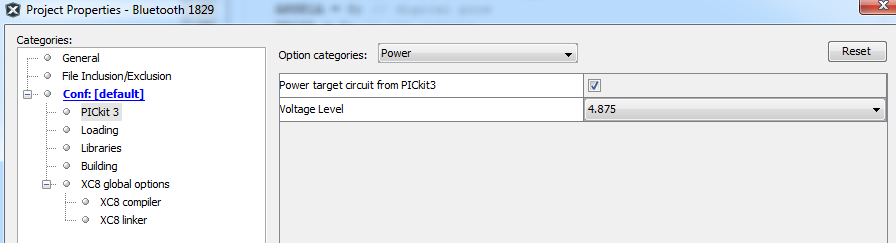
This is what it should look like when you are done:
Comments
BBCode Tags
| BBCode | Rendering |
|---|---|
| [b]bolded text[/b] | bolded text |
| [i]italicized text[/i] | italicized text |
| [u]underlined text[/u] | underlined text |
|
Auto link already enabled. |
http://example.org |
|
Auto image already enabled. |
 |
| [code=php]<?php echo 'Hello!'; ?>[/php] | |
| [quote]quoted text[/quote] | quoted text |
|
[list] [*]Entry 1 [*]Entry 2 [/list] |
|