MSP430 3-axis Accelerometer and Gyroscope Example Driver using the LSM6DS0
May 22, 2016 By justin bauer
This post will detail how to connect an STMicro LSM6DS0 accelerometer and gyroscope to an MSP430G2553 and display its data on a GUI in real-time. The built-in GUI Composer inside of Code Composer Studio will be used to rapidly graph the accelermoter and gyroscope X,Y,Z coordinates. I will be using the STEVAL-MKI161V1 Adapter Board since it comes in a easy-to-use development board that can be readily attached to a breadboard for prototyping. The 14-pin board is relativly cheap around $16 each from mouser.
The MSP430 will be communicating with the sensor via a 4-wire SPI implementation at 500kbps. The MSP430 will also be running at 16MHz (its fastest). The sensor is setup to sample its environment at 238Hz (238 samples per second), which is faster than what I experimentally determined the MSP430 is actually sampling the sensor. The sensor is sampled ~111 times per second. The gyroscope's output will be integrated to find displacement.
The LSM6DS0 has a ton of extra functionality that I will not be implementing such as a 32-bit deep FIFO, interrupts on thresholds met, filtering, temperature indicator, etc. All of these features are paramount if you wish to design a low-power application that cannot waste precious power in keeping the sensor above is "power-down" state and have the micro constantly poll the sensor for whenever it is jostled. This sample application merely gets the data from the sensor and plots it as fast as possible. This gives the designer a good launch point in starting a larger, more complex program. I figured that going too in-depth on these tutorials beings to limit the audience of the post. If you want to see something more detailed, please leave a comment below.
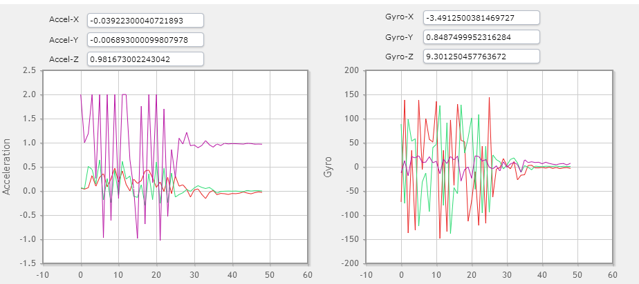
Below is what you can expect from the GUI, except updating every 200ms.
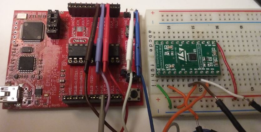
Here is the (messy) hardware setup. There really are not a lot of connections needed, its just that I'm messy
I've also made a youtube video.
Hardware Setup
The hardware interface is straightforward. Connect the USB to the MSP430 Launchpad to enable debugging and GUI data. I will be using SPI for ease-of-use for the demo which requires 4 wires. I attached the LSM6DS0 to the MSP430 via some alligator clips. This enabled me to freely move around the sensor to see the different readings.
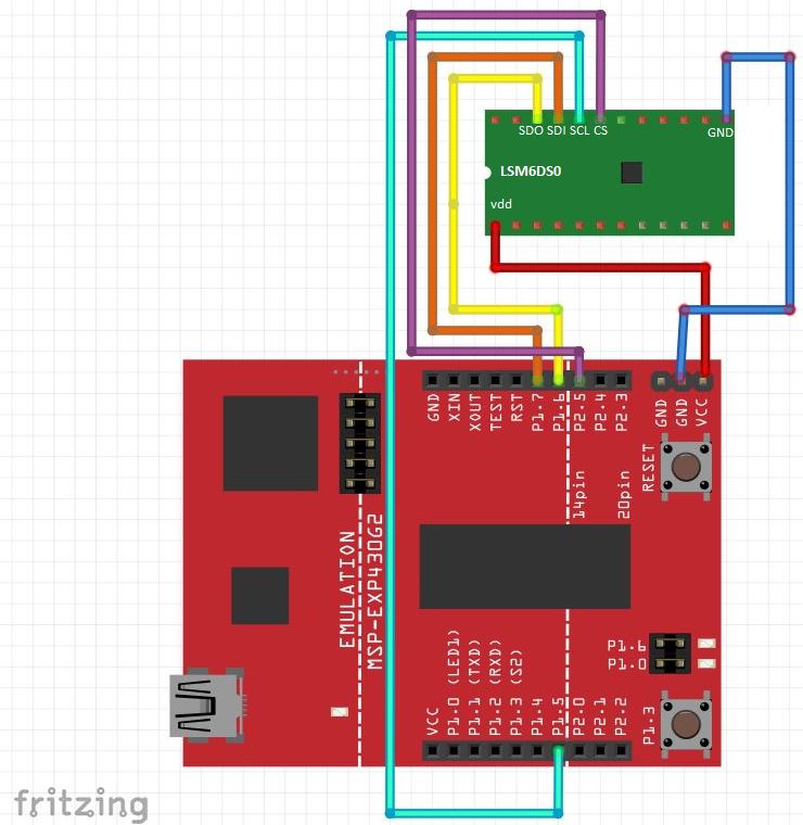
Here is the pinout for USCIB0 to the sensor:
| MSP430 | LSM6DS0 | Purpose |
|---|---|---|
| P2.5 | 19 | CS - Chip Select |
| P1.5 | 20 | SCL - Master Clock |
| P1.7 | 21 | SDI - Slave data in / Master out |
| P1.6 | 22 | SDO - Slave data out / Master in |
| VCC | VDD | VDD - Power |
| GND | GND | GND - GND |
Software Setup
I will be using TI's Graphical Peripherial Configuration Tool called Grace. You must download the plugin inside of Code Composer Studio. See this beginner tutorial on setting up Grace if you need help. I'm using the graphical tools since it makes it easy to setup and edit without too much work. Alternatively, you can look up the datasheet for the respective registers for each module and write to them directly. Grace just adds a nice front-end to that.
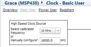
Clock
Setup the clock to run at its maximum at 16MHz.
UART
Setup the hardware uart to be used for sending our sensor data to a connected PC at 9600 baud. Make sure to rotate the jumpers on the launchpad. Please see this guide to learn how depending on your hardware version.
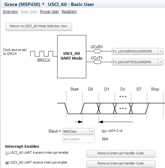 Make sure that the RX interrupt is enabled. This will allow the attached GUI to also modify the code while it is running like clearing variables and such. Don't generate the
 TX handler since the code will merely poll for it to be finished sending.
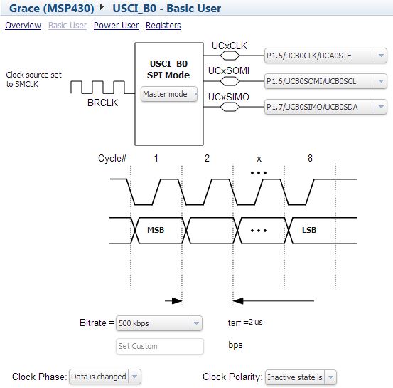
SPI
The sensor is connected to the G2553 via 4-wire SPI. We cannot use the built-in chip select (CS) since it conflicts with the already used UART above. Instead, we will be using another pin to manually control this. Note that the MSP430 is the "master" and LSM6DS0 as the "slave".
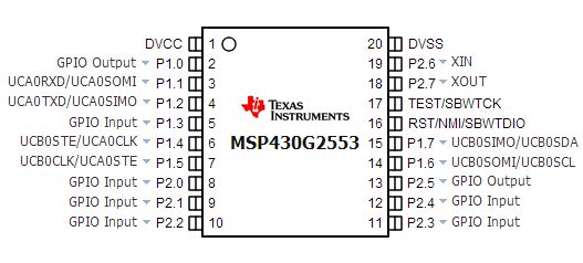
I/O
The I/O ports get automatically configured when other peripherals are setup. For example, setting up the SPI module should have already configured the associated pins as digital outputs (UCB0CLK,UCB0SOMI,UCB0SIMO). Setup P2.5 as a general purpose output. You pins should look as follows:
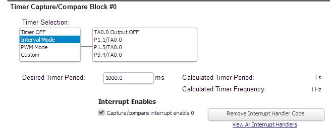
Timer
I always like to use a blinking LED to indicate to me that the program is running. I use Timer0 to create a 1 second interval that toggles the onboard red LED in the auto-generated InterruptVectors_init.c file.
LSM6DS0
The driver file is based on the registers and their bit defintions from reading the datasheet. The LSM6DS0_Platform.h file was primarily built from existing sources based on STMicro's Nucleo Sensor Shield. The actual driver is basic in its funcionaity in that it doesn't use much of the sensor's features as already described in the beginning of this article.
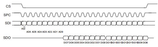
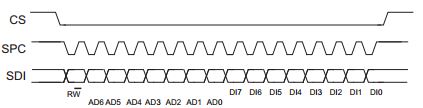
The driver has several internal functions to facilitate writing and reading from the LSM6DS0 via SPI. The R/W bit is sent first (0=write/1=read) and then MSb->LSb. Multiple bytes can be written or read without needing to change the address. The helps alleviate the bandwidth needed to read the 16-bit x,y,z registers.
SPI Read
The driver does multiple byte reads when possible according to the datasheet.
extern void read(uint8_t* readData, uint8_t addr, uint8_t numBytes){
	uint8_t i;
	uint8_t tmp;
	SELECT();
	__delay_cycles(1000);
	setReadMode(addr);
	for(i = 0; i != numBytes; i++){
		*readData = readByte();
		readData++; // increase to next address
	}
	__delay_cycles(1000);
	DESELECT();
}
I've placed some __delay_cycles() macros throughout the code to ensure correct timings. The actual delay can be played with or even omitted if you like. A 1000 cycle delay equates to 62.5uS delay ((1/16MHz) * 1000).
SPI works by shifting data between master and slave. The slave must shift in data in order to receive any data. This is why the readByte() function sends out dummy data seen below.
static uint8_t readByte(){
	__delay_cycles(1000);
	while (!(IFG2 & UCB0TXIFG)); // TX buffer ready?
	UCB0TXBUF = 0xAA; // send garbage
	while (!(IFG2 & UCB0TXIFG)); //  TX buffer ready?
	while (!(IFG2 & UCB0RXIFG)); //  RX Received?
	__delay_cycles(1000);

	return UCB0RXBUF; // Store received data
}
The UCB0TXIFG flag is SET whenever the buffer can accept new data. This does NOT mean that it is finished sending.
SPI Write
Writing a byte is similar to reading a byte, except the code does not wait for the RX flag to be set before returning.
static void writeByte(uint8_t data){
	__delay_cycles(1000);
	while (!(IFG2 & UCB0TXIFG)); // TX buffer ready?
	UCB0TXBUF = data; // send data
	while (!(IFG2 & UCB0TXIFG)); //  TX buffer ready?
	__delay_cycles(1000);
}
LSM6DS0 Init
The sensor is first detected to see if is attached. It does a simple 8-bit read of the WHO_AM_I register and compares it to a known value. It then turns ON the accelerometer and gyroscope at an Output Data Rate (ODR) of 238Hz. I also enabled the high-pass filter for the gyroscope to smooth out some of the readings. FIFO is bypassed and the new data is simply written over the old.
extern int8_t LSM6DS0_Init(){
	uint8_t deviceId;

	read(&deviceId, LSM6DS0_XG_WHO_AM_I_ADDR, 1); // First detect if module is attached

	if(deviceId != I_AM_LSM6DS0_XG)
		return -1; //error


	writeRegister(LSM6DS0_XG_CTRL_REG1_G, LSM6DS0_G_ODR_238HZ); // enable both gyro and accel at 238 Sampling rate (~4-8mA runtime)
	writeRegister(LSM6DS0_CTRL_REG3_G, HP_EN | 0x00); // enable high-pass filter for gyro
	writeRegister(LSM6DS0_FIFO_CTR, 0x00); // Bypass mode, turn of FIFO

	return 1; // success
}
Gyro/Accel readings
A global structure consisting of floating point members for each of the linear acceleration and angular velocity axis is passed by reference into the accelLoad and gyroLoad functions. These each read the signed integer 16-bit value out from the sensor starting with its LSB. Depending on the linear and angular measurement range, the raw data must be multiplied by a sensitivity value to convert it to the correct unit. For the accelerometer, it is mg/LSb (milli 'g') and for the gyro it is mdps/LSb (milli degrees-per-second). I am using the default values for both so I would have to multiply the acceleration value by 0.061 and then divide it by 1000 to convert to the regular 'g' value. Likewise, the code multiplies the raw gyro readings by 8.75 and divides by 1000 to convert to degrees-per-second.
/**
 * Get all 3-axis accelerometer readings. Convert from mg to g.
 */
extern void accelLoad(accel_gryo_str* x_gyro){
	int16_t tmp;

	read((uint8_t*)&tmp,LSM6DS0_XG_OUT_X_L_XL, 2);
	x_gyro->accel_x = (tmp * 0.061) / 1000.0;
	read((uint8_t*)&tmp,LSM6DS0_XG_OUT_Y_L_XL, 2);
	x_gyro->accel_y = (tmp * 0.061) / 1000.0;
	read((uint8_t*)&tmp,LSM6DS0_XG_OUT_Z_L_XL, 2);
	x_gyro->accel_z = (tmp * 0.061) / 1000.0;
}

/**
 * Get all 3-axis gyro readings. Convert from mdps to dps.
 */
extern void gyroLoad(accel_gryo_str* x_gyro){
	int16_t tmp;;

	read((uint8_t*)&tmp,LSM6DS0_XG_OUT_X_L_G, 2);
	x_gyro->gyro_x = (tmp * 8.75) / 1000.0;
	read((uint8_t*)&tmp,LSM6DS0_XG_OUT_Y_L_G, 2);
	x_gyro->gyro_y = (tmp * 8.75) / 1000.0;
	read((uint8_t*)&tmp,LSM6DS0_XG_OUT_Z_L_G, 2);
	x_gyro->gyro_z = (tmp * 8.75) / 1000.0;
}
The sensor, like us humans, will always be experiencing a constant acceleration due to gravity equal to 1g. Moving the sensor up and down violently will increase the amount of 'g's experienced by the sensor. The maximum is +/-2G for the default setting, but it can be increased for sensitivity up to 16G which is a LOT of acceleration. Rotating the sensor add a slight speed will cause the gyro output to increase. The faster you go, the higher the peak value up to +/-245dps.
Main Routine
The main file defines the gyro and acceleration data structure and the displacement angle as globals to be printed to the GUI Composer. They must be globals in order for the GUI to update correctly. In order to create an accurate integrate routine, I must know how often the sensor can be sampled. I create a variable that is incremented until 1 second has elapsed. This value happens to equal 111. I use this as the defined SAMPLE_RATE.
// Globals to be printed to GUI Composer (must be global!!)


accel_gryo_str x_gyro;	// main gyro struct that contains all sensor outputs

/*
 * Integrate the gyro Z-axis in order to get displacement. This gets
 * full of error if left integrating too long. Future code should
 * clear it after a timeout has occurred. For now this will d
 */
float angle = 0;

/*
 * In order to find the actual sample rate, increment this variable and then place a
 * debug point in the 1 second ISR. Look at how many counts occured in the main loop
 * and then use this to number to integrate the gyro sensor input. The end result is
 * an approximate displacement angle from velocity.
 */
uint32_t counts;
#define SAMPLE_RATE	111 // experimentally determined
The gyroscope will always have some undetermined offset upon power-up. The mainline code will first read this offset so it can be subtracted from subsequent readings. The while(1) loop simply gets the data and calculates the displacement of the gyro by integrating its velocity to get displacement. This is a well known technique, but it is prone to error, especially over long periods of time. This is why every 10 seconds, the code will clear this variable back to 0 degrees as long as the sensor is determined to be at rest.
int main(void)
{

	float offset;	// record the gyro offset on startup in order to minimize integration error over-time
    Grace_init(); // Activate Grace-generated configuration
    LSM6DS0_Init(); // initialize sensor
    gyroLoad(&x_gyro);			// get the gyro readings
    offset = x_gyro.gyro_z;		// Set the original offset

    // Constantly read sensors and wait for 2 full rotations before turning on an LED
    // If accelerometer is moved in any axis to +1.7G and then to -1.7G, toggle another LED
    while(1){
    	accelLoad(&x_gyro); // get accelerometer results
    	gyroLoad(&x_gyro); // get gyro results
    	angle += (x_gyro.gyro_z - offset) / SAMPLE_RATE; // get angle displacement
    	//counts++;		// testing!
    }
}
GUI Composer
Part of the reason why I chose to use the MSP430 for this endeavour was because I can EASILY graph the data without needing to code an additional GUI using C#, Qt, Java, LabVIEW or whatever. I am not going to detail how to set this up since my previous post already details how to do so. I will be using the exact same techniques, however just adding a few more variables to the mix. You must also add the two Serial_Cmd_Monitor.c/.h files as well as the uart.c/h files which send and receive data for the GUI. These changes are mandatory to get the GUI to work correctly.
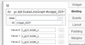
I used 2 ScalarLineGraphs and numerous TextBoxs to show the data. Each graph will plot 3 floats via their Binding. Simply type in the data structure that was defined in main.c.
I also edited the app.json file to update the GUI every 200ms instead of the default 1.5 seconds.
Once finished, down the project and click the Play button to have the code run. Once running, highlight the UARTConnection_0/ComPort in the debug console and then make sure to click Run->Load->Load Symbols and select your .out file. Then navigate back to GUI Composer and click the "preview" button in the top-right.
It is kinda clunky to get working the first few times. It is a beautiful sight when it does work and helps greatly in debugging or adding features to your applications.
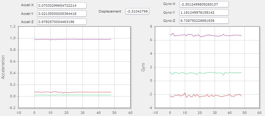
Red = X-axis Green = Y-axis Purple = Z-axis
Move the sensor up and down. You should see the purple line on the acceleration raise up and down. This should read close to 1 when at rest assuming the pins are face down and the sensor is facing the sky. Try rotating the sensor at a fast speed and notice the gyro output - it should increase and then settle back down close to zero. The displacement angle should increase or decrease depending on the direction your turned.
 It should clear back to 0 after 10 seconds if the code senses that it isn't being currently moved. This is done the ISR. Both of the graphs should auto-scale both of the axis. I wanted to only scale the x-axis and not the y-axis, but was unable to do so in the GUI Composer for some reasons and it wouldn't work. Leave a comment if you know how.
Improvements
The code can be improved in a few ways
- Make it "low power" by keeping the micro at sleep for most of the time and have it wake up periodically to take a reading OR utilize the interrupts on the LSM6DS0 to trigger an output when a certain threshold has been reached.
- Allow more options in configuring the LSM6DS0. Right now I mostly use the default settings.
- Use the 32-byte deep FIFO
Please leave a comment for suggestions or you are having problems replicating the graph.
Comments
BBCode Tags
| BBCode | Rendering |
|---|---|
| [b]bolded text[/b] | bolded text |
| [i]italicized text[/i] | italicized text |
| [u]underlined text[/u] | underlined text |
|
Auto link already enabled. |
http://example.org |
|
Auto image already enabled. |
 |
| [code=php]<?php echo 'Hello!'; ?>[/php] | |
| [quote]quoted text[/quote] | quoted text |
|
[list] [*]Entry 1 [*]Entry 2 [/list] |
|