MSP430 Launchpad - Blinking your First LED
Mar 23, 2016 By justin bauer
This post covers how to quickly get started using the MSP430 Launchpad. There are several variations of the Launchpad now circulating ever since its launch in 2010. I will be using the popular MSP430G2552, which is usually categorized under the MSP430G2XX series. You can easily start playing with one of these at a nearby hackerspace or on digikey for only $10.
The G2553 is a fairly basic 20-pin, 16-bit microcontroller. It run at 16MHz with 16KB of flash and 500 bytes of RAM. Its onboard communication modules (1x I2C, 2x SPI, 1x UART) come in handy when interfacing to a computer or other devices such as EEPROM or BLE device.
The best feature of the launchpad is that is already has an integrated debug interface which means that you don't need to purchase an additional $50+ programmer to get started. This feature also allows you to set breakpoints and single step through your code with no overhead on your program. In case you are wondering, TI most likely is selling this at a loss to get people interested in their product. I'm not complaining.
Install
Once you have your DIP package onto the female slot, go ahead and connect the included mini USB connected to your computer. My windows 7 machine did not immediately recognize the device, but that is OK since we need to download TI's IDE anyways which will probably include the needed drivers for us to debug and run the compiled code. You can download Code Composer Studio (CCS) on their wiki. The software works on both windows and linux. As of this writing, version 6.1.2 is the latest that I downloaded. I also used the web installer since I'm currently connected to the internet.
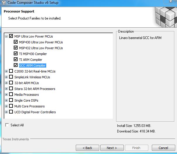
I went ahead and choose to install all of the Ulta Low Power Compilers. Please note that you will have to explicitly check the GCC ARM Compiler.
In the next screen I opted to install the GCC toolchain, although I don't know what the difference is between this and the last picture as shown.
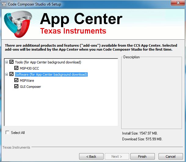
The GUI Composer creates a nice visual view into your embedded system. I haven't used it yet, but it looks like it could be useful for when you want to simply graph some debug data such as an ADC output or uart rx/tx data.
MSPWare is a good option to download as well in order to quickly get started.
MSPWare is is a collection of user’s guides, code examples, training, and other design resources for ALL MSP devices delivered in a convenient package.
I was able to seamlessly integrate one example from this repository within seconds. The only downside of this is that the number of projects were limiting.
The install will take around 10 minutes to install and register everything.
Using Code Composer Studio (CCS)
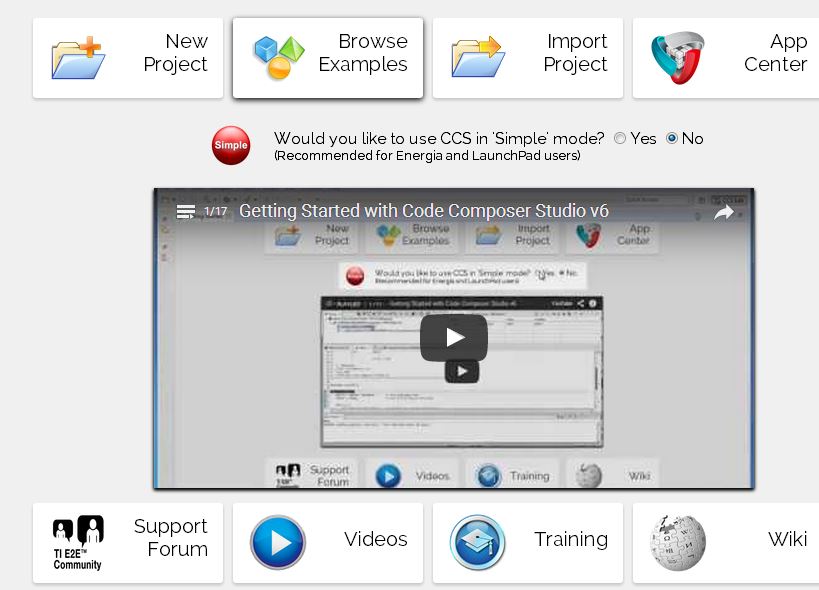
From the Getting Started page, click on the CCS App Center and search for Grace. Select the checkbox to install and restart the software when finished.
Grace is a visual code generator that also contains excerpts from the datasheet. I've noticed microcontroller vendors leaning towards these automatic code generator tools more and more. Microchip Technology has their equivalent called the "Microchip Code Configurator (MCC)" inside of MPLABX as a netbeans plugin and Renesas's Peripheral Driver Generator. These visual aids are great to get your drivers and bare necessities such as clock oscillators and pins setup without having to look too deep into the 100's of pages long datasheet.
Then click the Browse Examples. This should launch you into a new tab where you can filter by specific devices. Recall that we are using the MSP430G2553.
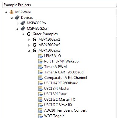
Go ahead and open WDT Toggle and import the example project into CCS. You should notice a new project in your project explorer now title, msp430g2xx3_wdt_toggle_pin. Expand the single source file in that project. Click the green bug on the toolbar to build and program your MSP430 via the on-board bootloader. You should see the red LED1 flash at a rapid rate. Congratulations!
This code works by using a timer called the Watchdog Timer (WDT) to toggle an LED every 30ms. The pin will be set (turned HIGH) and then cleared (turned OFF) within 30ms of each rising/falling edge. A full period would be 60ms which yields a frequency of ~16Hz so you can visible see the LED flashing. The WDT is on nearly every microcontroller. It is commonly used as a safety feature to ensure that the microcontroller does not get "stuck" anywhere in the code. If the firmware does not clear the timer ("kick the dog") before it rolls over, then the microcontroller will reset and raise an alarm in the code somewhere that something went terribly wrong.
Please note that I am using the optimized TI Compiler, which is free for Launchpad customers up to 16KB of flash. This should be plenty for evaluation purposes. I recommend using the freely available GCC compiler for larger projects.
The code is farily basic.
 * ======== Standard MSP430 includes ========
 */
#include
#include
/*
 * ======== Grace related declaration ========
 */


/*
 *  ======== main ========
 */
int main(void)
{
	Grace_init();
    __bis_SR_register(LPM0_bits + GIE);                 // Enter LPM0 w/ interrupt
}
It includes the device specific header file which holds the register address and the Grace.h file which includes the peripheral library code that was generated. The first call is to the Chip Configuration API which will configure the peripherals necessary to blink the LED. The next line puts the microcontroller to sleep in its low power state. The MSP430 is still capable of running its peripherals even though the CPU is asleep.
Improving the Demo
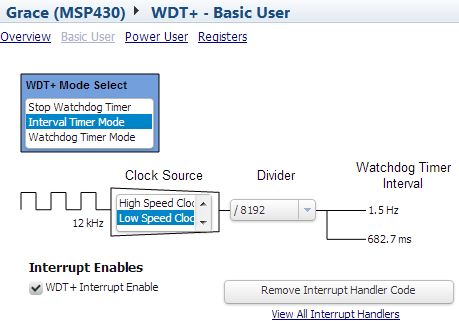
Lets modify this demo slightly so as to better understand how to use this magical code configurator. Double click on msp430g2xx3_wdt_toggle_pin.cfg to open up the configuration file in Grace. Here you will see an overview of the module and some of its use cases. I think this is brilliant and really helps you from going back and forth from the datasheet. Nice job TI! Anyways, click the little arrow in the header and select WDT+. Then click Basic User. Change the Clock Source to Low Speed Clock. You should notice how the watchdog timer interval has now changed to 1.5Hz.
Click that down arrow again and navigate to Interrupt Vector List. Click Open Interrupt Vector File and notice how the default code already has code to toggle a pin in its interrupt service routine (ISR). This is where the other half of the magic happens where the LED is toggled.
#pragma vector=WDT_VECTOR
__interrupt void WDT_ISR_HOOK(void)
{
    /* USER CODE START (section: WDT_ISR_HOOK) */
    P1OUT ^= 0x01;                            // Toggle P1.0 using exclusive-OR
    /* No change in operating mode on exit */
    /* USER CODE END (section: WDT_ISR_HOOK) */
}
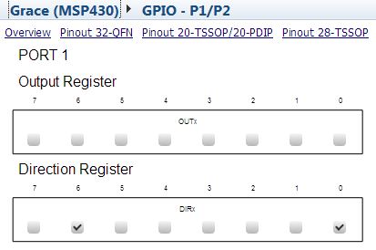
If you still want to go further, like blinking the 2nd LED, you will have to open up the Direction Register in the configurator tool and then toggle P1.6 (PIN6) in that same ISR.
P1OUT ^= (BIT0 | BIT6); // toggle both LEDs //(BIT0 | BIT6)
Now both of the LEDs light up at the same time. A green and red one, which together make it appear yellow.
I've pasted below sample code that basically does what the code generator project achieves above. In this code, the same watchdog timer is used to fire an interrupt every 250ms and then toggle the P1.0 output.
#include


int main(void)
{
  WDTCTL = WDT_ADLY_250;                    // WDT 250ms, ACLK, interval timer
  IE1 |= WDTIE;                             // Enable WDT interrupt
  P1DIR |= 0x01;                            // Set P1.0 to output direction

  __bis_SR_register(LPM3_bits + GIE);       // Enter LPM3 w/interrupt
}

// Watchdog Timer interrupt service routine
#if defined(__TI_COMPILER_VERSION__) || defined(__IAR_SYSTEMS_ICC__)
#pragma vector=WDT_VECTOR
__interrupt void watchdog_timer(void)
#elif defined(__GNUC__)
void __attribute__ ((interrupt(WDT_VECTOR))) watchdog_timer (void)
#else
#error Compiler not supported!
#endif
{
  P1OUT ^= 0x01;                            // Toggle P1.0 using exclusive-OR
}
Comments
BBCode Tags
| BBCode | Rendering |
|---|---|
| [b]bolded text[/b] | bolded text |
| [i]italicized text[/i] | italicized text |
| [u]underlined text[/u] | underlined text |
|
Auto link already enabled. |
http://example.org |
|
Auto image already enabled. |
 |
| [code=php]<?php echo 'Hello!'; ?>[/php] | |
| [quote]quoted text[/quote] | quoted text |
|
[list] [*]Entry 1 [*]Entry 2 [/list] |
|