SMS example using Tiva C LaunchPad and SIM 808 GSM Module
May 02, 2017 By Waleed Nassar
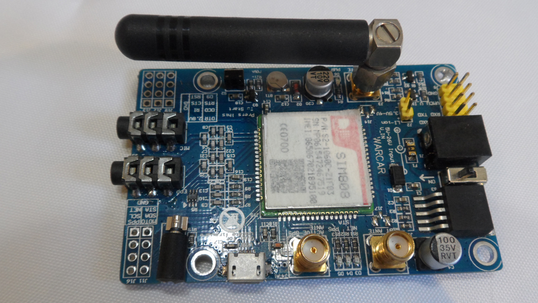
In this article we will use the SIM808 evaluation board (evb-v3.2) to interface with the TM4C123GH6PM microcontroller to send and receive a simple SMS text. The code is applicable to any evaluation board of the SIM808 module. The TM4C123GH6PM microcontroller is an ARM architecture controller, so it will also be a good opportunity to get familiar with the ARM architecture. For ease of development this microcontroller is available on an evaluation board that has the pins easily available and an on-board debugger where you can perform in-circuit debugging without a programmer. I'll be using the TM4C123G which is one of the Tiva C series LaunchPads.
Here is a short video showcasing the entire demo
The Tiva C Launchpad that we will be using

SIM 808
The SIM 808 is an integrated module that contains a GSM, GPRS, GPS and a Bluetooth module. It is very useful when you need to add any of these communication methods to your embedded system. You can for example enable your system to send or receive SMS, send HTTP data over the internet, and get GPS location from your mobile via Bluetooth.
The configuration is done via AT commands. These special commands are sent to the module to instruct it to configure its internal state machine. This is similar to how the the popular HC-05 Bluetooth module works and many more such devices. For example, the command AT+CGMS sends an SMS message. The command AT+CPMS chooses the preferred SMS message storage. In this article we will use the UART to send these commands to the SIM808 from the microcontroller.
UART on TM4C123GH6PM
UART is a full duplex asynchronous serial communication protocol that is widely used to communicate with different modules such as Bluetooth and GSM modules such as the SIM900 and SIM808. The TM4C123GH6PM has 8 UART modules, but we will only be using 1 of them.
Baud rate Generation
To configure this rate on the TM4C123GH6PM you need to fill in registers UARTIBRD (UART Integer Baud Rate Divisor) and UARTFBRD (UART Fractional Baud Rate Divisor) with the proper values. The values to be written to these registers can be calculated using the below equation:
UART1BRD=Integer(UARTSysClk/ClkDiv * Baud_Rate) where
UARTSysClk = Clock used to drive the UART module. In this article we are using the default system internal oscilator which is 16 MHz
ClkDiv = Clock Division factor. The system clock is divided by this number before being applied to the UART module. This number takes the value of 8 if we set the HSE bit in the UARTCTL register or 16 if we clear this bit. In this article we will clear this bit, so the ClkDiv value is 16.
Baud_Rate = Bit speed transmission. In This article we will use one of the widely used rates that of 9600 bits per second
Plugging in the numbers yields a register value of 104 from 104.1667. Note that we only write the integer value here.
UARTFBRD=Integer((UART1BRD * 64) + 0.5)
Plugging in the numbers yields a register value of 11 from 11.1667
Enabling UART Module
- Enable the module and provide it with a clock by setting the proper bit in the
RCGCUARTregister. TheRCGCUARTRegister has 8 modifiable bits, each bit corresponds to a UART module. To enable Module 1 we set bit 1 in this register. - As the UART, module 1, pins are multiplexed on
PB0andPB1(Port B-Pins 0&1), then we need to enable clock to theGPIOBmodule, enable the digital functionality and the alternate function of those pins by configuring the registers (RCGCGPIO,GPIODEN,GPIOAFSELandGPIOPCTL) - To enable
GPIOB, set bit 1 in theRCGCGPIOregister. - To enable the digital functionality for pins 0&1 of Port B, set bits 0 & 1 in the
GPIODENregister for port B. - To enable the alternate function for pins 0&1 of Port B, set bits 0 & 1 in the
GPIOAFSELregister for port B. - To choose UART as the alternate function for pins 0&1 of Port B we need to place a value of 1 in the Port Mux Control field corresponding to each pin in the
GPIOPCTL(GPIOPort Control) register. Accordingly, we need to set bits 0 and 4 of this register.
Configuring UART protocol parameters
- Before starting the UART parameters configuration we should first disable the UART protocol. We will re-enable it again once the configuration is complete. Disabling it is done by clearing bit 0 (
UARTEN) in theUARTCTL(UART Control) register. - Write the values we calculated above for the registers
UARTIBRDandUARTFBRD. This step must be done before writing any values toUARTLCRHregister, because values written to these registers (UARTIBRDandUARTFBRD) are committed only after writing to the UARTLCRH register - Configure UART word length of 8 bits which is usually the standard length.
- Configure the UART clock source by writing to the
UARTCCregister. In this article we will use the system clock, so we will write a value of 0x00 to this register. - In the
UARTCTLregister: a. Set bits 8 & 9 (TXE&RXE bits) to enable transmit and receive sections of the UART module. b. Clear bit 5 (HSEbit) to indicate a clock divisor of 16. c. And finally, Set bit 0 (UARTEN) to re-enable the UART module.
void UART_Init (void)
{
SYSCTL->RCGCUART|=(1<<1); //Enable and provide clock UART Module 1
SYSCTL->RCGCGPIO |=(1<<1) ;//Enable and provide clock to Port B
GPIOB->AFSEL|=(1<<0)|(1<<1); //Enable Alternate function for Pins 0& 1 of Port B
GPIOB->PCTL|=(1<<0)|(1<<4); //Choose UART as the alternate function for Pins 0& 1 of Port B
GPIOB->DEN|=(1<<0)|(1<<1); // Enable Digital functionality for Pins 0& 1 of Port B
UART1->CTL &=~(1<<0); // Disable UART protocol
UART1->IBRD=104; //Write the UARTIBRD value for the Baud Rate (Assuming Baud rate of 9600)
UART1->FBRD= 11; //Write the UARTFBRD value for the Baud Rate (Assuming Baud rate of 9600)
UART1->LCRH=0x60; //Set bits 5&6 to indicate a word length of 8 bits and clear all the other bits of the UARTLCRH register
UART1->CC= 0x00; // Choose System clock as the UART Clock Source
UART1->CTL=0x301; //Write bit values to the UARTCTL register as clarified in step 6.
}
Sending UART Messages
In order to send a message via UART all you need is to put the character in the UART Data Register. However, you first need to ensure that the register is not already full, otherwise your data may be ignored. You can continuous check bit 5 (TXFF) of the UARTFR (UART Flag Register). This bit is set by the MCU when the transmission register is full and can't receive any more data to send. The bit is cleared when the register is ready to receive new data.
The application code here will poll this bit until it is cleared before putting new data into the UART Data Register (UARTDR).
Note: Polling a bit is not ideal for a responsive system. It is quick and easy to implement for a simple application, however.
We will use the below code for the UART send function:
#define get_bit(reg,bitnum) ((reg & (1<<bitnum))>>bitnum) // Macro used to get the value of a certain bit in a register

void UART_SendChar (char data)
{
  while (get_bit(UART1->FR,5)==1)  //Poll on bit 5 (TXFE) until it becomes 0. The loop exits only if the bit value is 0
  {
  }
  UART1->DR=data; // Put the data to send in the UARTDR register
}
You may need more than just sending one character in an actual application. When you are using AT commands, to configure the GSM module for example, you will frequently need to send strings. Sending a string is actually a repetitive process of sending a character using the above explained function (UART_SendChar). A string is always terminated by a "Null" character. To send a string we can simply create a loop that keeps sending characters until a Null character is met. This is exactly what we do in the below shown function code (UART_SendStr)
{
  char i=0;
  while (*(string+i) != '\0')
  {
    UART_SendChar(*(string+i));
    i+=1;
  }
}
Receiving UART Messages
When the UART module receives a message (1 byte), it is written to the UART Data Register (UARTDR). To receive a new message you just need to read UARTDR. First you should make sure that the register is not empty by checking bit 4 (RXFE) of the UARTFR (UART Flag Register). This bit is set by the MCU when the receive register is empty. We will poll on this bit until it is cleared and then read from UARTDR. The below code shows how to implement this function:
void UART_RecChar (char* data) //Input to the function is a pointer to a memory place to save the received data in
{
  while (get_bit(UART1->FR,4)==1) //Poll on bit 4 (RXFE) until it becomes 0. The loop exits only if the bit value is 0
  {
   }
  *data=UART1->DR; // Read the UARTDR which contains the received data, and write it to the pointer provided by the function user.
}
This loop will run forever and the code will get stuck in this function if a UART message never arrives. We will create a decrementing counter to act as a timeout for the loop to avoid this. In the below code, we wrote a function called (UART_RecCharwTimeOut) that performs a UART Receive with timeout. The function returns a null if nothing is received.
#define UARTSysClock 16000000UL //System Clock
#define UARTRecTimeOut 600 //timeout in ms after which UART_RcCharwTimeOut function returns. A null is returned if nothing is received.
#define get_bit(reg,bitnum) ((reg & (1<<bitnum))>>bitnum)
void UART_RecCharwTimeOut (char* data)
{
  int count=(UARTRecTimeOut*(UARTSysClock/1000))/3; // divided by 3 as the decrement takes 3 clock ticks
  while (get_bit(UART1->FR,4)==1&&count>0)
  {
    count--;
  }
  If (count==0)
  {
    *data='\0';
  }
  else
  {*data=UART1->DR;}
}
Receiving AT Commands responses
The responses we receive from the SIM808 usually consist of several characters and if the command is successfully executed, they contain the word "OK". The function below receives the command response, writes it in an array and returns 1 if the command is successfully executed and 0 if not.
char AT_Response (char *ATRes) //  *ATRes is a pointer to the start of the array where the response will be stored.
{
  char i=0;  // will be used as an index
  char ok=0;
  while (*(ATRes)=='\0')
  {
    do
    {
      UART_RecCharwTimeOut(ATRes+i); // Receive character using the UART_RecCharwTimeOut function and place it in tha array
      i++;
    }
    while(*(ATRes+i-1)!='\0'); // when nothing is receveived by UART_RecCharwTimeOut, a null is returned and saved in the array.

  }

 i=0; //reset the index to 0
 while (*(ATRes+i)!='\0')       // This loop searches for the word "OK" in the AT command response
    {
      if (*(ATRes+i)=='O' && *(ATRes+i+1)=='K' )
      {
        ok=1; // if "OK" is found, the variable named ok will be set to 1 otherwise it will stay 0.
        break;
      }
      i++;
    }
  return ok;    //ok variable is returned by the function
}
Now, we have all the functions we need to use UART for sending AT commands to the SIM808 module and receive responses. Now let's get to the initialization of the SIM808 module.
SIM808 Initialization
Before starting to work with the SIM808 module, we need to do a few configurations as below:
- Ensure that the module is on and ready to communicate. This is done by sending the command AT and waiting for a response of "OK" from the module.
- Turn off command echo. This is enabled by default so that it always replies back with the characters sent to it. This is useful when we are communicating with the module from a computer screen and figuring out if the module works or not. We turn that off by sending the AT Command (
ATE0).
void delay_ms (int time_ms) // Delay function using the timer. the input to the function is the required delay in milliseconds
{
  SYSCTL->RCGCTIMER=0x01;
  TIMER0->ICR|=(1<<0);
  TIMER0->CTL=0x00;
  TIMER0->CFG=0x00;
  TIMER0->TAMR=0x01;
  TIMER0->TAILR=(16000000UL/1000)*time_ms;
  TIMER0->CTL|=(1<<0);
  while (get_bit(TIMER0->RIS,0)==0)
  {}
}
void GSM_Init(void)
{
  char confirm=0; // Will be used to store the return value of the AT_Response function
  char ATResponse[8]={0}; // will be used to store the AT command response that is also coming for the AT_Response function
  char ATEResponse[8]={0}; // will be used to store the ATE0 command response
  char trial=1; //Will be used to count the number of trials to send the AT command and successfully receive an "OK" response.

 while (confirm==0 && trial<=3) // a Maximum of 3 trials is allowed, then the function exits.
 {
    UART_SendStr ("AT\n \r"); // Send "AT" Command
   confirm=AT_Response(ATResponse); // Receive the response and write it to ATResponse array. The function return value is stored in the variable "confirm"
   trial++; //Increment the number of trials

 }
 delay_ms (500); //Allow a delay of 500 ms before sending the next command
 confirm=0;trial=1; // reset the values of confirm and trial
  while (confirm==0 && trial<=3) // a Maximum of 3 trials is allowed, then the function exits.
 {
   UART_SendStr ("ATE0\n \r"); // Send "ATE0" Command
   confirm=AT_Response(ATEResponse); // Receive the response and write it to ATEResponse array. The function return value is stored in the variable "confirm"
   trial++; //Increment the number of trials

 }
}
By now, we are done initializing the SIM808 module. Let's proceed to reading a received SMS.
Reading a newly received SMS
New SMS Notification Te SIM808 sends the below string via UART as a new SMS notification:
/r/n+CMTI: "SM",10/r/n
| \n | +CMTI: | "SM", | 10 |
|---|---|---|---|
| New Line character | Notification of a new SMS arrival | Memory Type where the new SMS is stored. "SM" = SIM card memory. It could also be "ME" = module memory | Index of the message in the memory. It is used to refer to the message when reading it. |
We will save this response to an array and pick up the information we need from it. The characters order in the array will be as shown below:
| Character | \r | \n | + | C | M | T | I | : | " | S | M | " | , | 1 | 0 | \r | \n | |
|---|---|---|---|---|---|---|---|---|---|---|---|---|---|---|---|---|---|---|
| Index | 0 | 1 | 2 | 3 | 4 | 5 | 6 | 7 | 8 | 9 | 10 | 11 | 12 | 13 | 14 | 15 | 16 | 17 |
AT Commands to read an SMS
To read an SMS you need to send the below AT Commands in order:
-
AT+CPMS="SM": This command sets the preferred memory type as the SIM card memory. The next read operation will be from the SIM card memory. -
AT+CMGF=1: This command sets the message format as Text. -
AT+CMGR=Message Index: This command instructs the module to start sending the SMS content.Message Indexis the number received in the CMTI message as explained above.
The Memory type and message index information will be got from the CMTI message explained before, where: characters (9-12) are the memory type and characters (14-15) are the message index. We can send the three AT commands in one line in the below format for faster and more efficient communication
AT+CPMS="SM";+CMGF=1;+CMGR="Message Index"
The expected response:
+CPMS: 10,30,10,30,10,30
+CMGR: "REC READ","+201009797626","","17/04/24,15:18:33+08"
"Message Text"
The first line in this response shows the number of SMSs in the memory and the capacity of the memory. There are 10 SMSs in the memory and its capacity is 30 SMSs. The Second line shows the following information:
- SMS status: REC READ means the SMS is Received and Read
- Sender Number: +201009797626
- Date and Time of Receiving the SMS: 24th April, 2017- 15:49:30
The third line is the message text.
We will save this whole response in an array to pick the information we need from it. We can get the message text by searching for the 4th \n character and getting the characters after it till the next \r character. We can also get the sender number by searching for the 3rd + character and getting the characters after it till the " character.
Delete SMS
This can be done by sending the AT Command:
AT+CMGD="Message Index"
Receive SMS Code
The function code we are showing below (SMSReceive) performs the above explained steps.
It takes 2 array inputs (SMSReturn) and (Sender), it reads the SMS and saves the SMS content to SMSReturn and the number of the sender to Sender.
void SMSReceive (char* SMSReturn, char* Sender)
{
  char SmsNotification[17]={0}; // Will be used to store the CMTI message
  char SmsText[110]={0}; // Will be used to store the Sms content
  char MemoryType[5]={0}; // Will be used to store the memory type
  char MessageIndex[6]={0}; // Will be used to store the message index
  char i=0; // Will be used as an index
  char j=0; // Will be used as an index
  char SmSReceived=0;  // Will be used to indicate that a new SMS arrived
  while (SmSReceived==0)  // This is an infinite loop that exits only if an SMS is received
  {
    i=0;
    do // This loop receives the CMTI message characters one by one and save it to SmsNotification
    {
      UART_RecCharwTimeOut(SmsNotification+i);
      i++;
    }
    while(*(SmsNotification+i-1)!='\0');
    if (*(SmsNotification+10)!='\0' && *(SmsNotification+11)!='\0' ) // Check that the message type (Characters 10 and 11) exists in the message
    {
      SmSReceived=1; // If Message type exists, then CMTI message is received. Set SmSReceived to 1 to exit the loop.
    }
  }
  *(MemoryType)=*(SmsNotification+9);  // Save the memory type characters to MemoryType Array
  *(MemoryType+1)=*(SmsNotification+10);
  *(MemoryType+2)=*(SmsNotification+11);
  *(MemoryType+3)=*(SmsNotification+12);
  *(MemoryType+4)='\0'; // To terminate the string
  i=0;
  while (*(SmsNotification+14+i)!='\r') // This loop gets the message index (starting at Character 14) and saves it to MessageIndex
  {
    *(MessageIndex+i) = *(SmsNotification+14+i);
    i++;
  }
  UART_SendStr("AT+CMGF=1;+CPMS="); //Start sending the AT Command
  UART_SendStr (MemoryType);
  UART_SendStr (";+CMGR=");
  UART_SendStr (MessageIndex);
  UART_SendStr ("\n\r");
  i=0;
  do // Receive the AT commands Response that contains the SMS Text
  {
    UART_RecCharwTimeOut(SmsText+i);
    i++;
  }
  while(*(SmsText+i-1)!='\0');
  i=0; // Reset index to 0
  j=0; // Reset index to 0
  do //This loop Searches for the 4th '\n' Character. When found its position index will be in i variable
  {
    if (*(SmsText+i)=='\n')
    {
      j++;
    }
    i++;
  }
  while (j<4);
  j=0; // Reset index to 0
  while (*(SmsText+i)!='\r') // This loop transfers the characters from the local array SmsText to the user array SMSReturn
  {
    *(SMSReturn+j)=*(SmsText+i);
    j++;
    i++;
  }
  i=0; // Reset index to 0
  j=0; // Reset index to 0
    do //This loop Searches for the 3rd '+' Character. When found its position index will be in i variable
  {
    if (*(SmsText+i)=='+')
    {
      j++;
    }
    i++;
  }
  while (j<3);
    j=0; // Reset index to 0
   while (*(SmsText+i)!='"') // This loop transfers the characters from the local array SmsText to the user array SMSReturn
  {
    *(Sender+j)=*(SmsText+i);
    j++;
    i++;
  }
//Delete the SMS
  UART_SendStr ("AT+CMGD=");
  UART_SendStr (MessageIndex);
  UART_SendStr ("\n\r");
}
SMS Sending
To send an SMS you need to send the below AT commands to the SIM808 module in order:
-
AT+CMGF=1: To set the SMS format as text. -
AT+CMGS="mobile number": To set the number that the SMS will be sent to. -
Message Text: The text we want to send -
0x1A: This number indicates end of the SMS and instructs SIM808 to send the SMS.
void SMSSend(char *Number, char *Text) // Number is a pointer to an array that holds the mobile number. While Text holds the SMS Text
{
  char CMGSResponse[25]={0}; // will be used to store the response of "AT+CMGS".
  char CMGFResponse[7]={0}; // will be used to store the response of "AT+CMGF".
  char SendingResponse [70]={0}; // will be used to store the response after sending the SMS.
  char confirm=0; // will be used to store the returned ok value from AT_Response function.
  Number++;
  UART_SendStr ("AT+CMGF=1"); // send (AT+CMGF Command)
  UART_SendStr ("\n \r");
  confirm=AT_Response (CMGFResponse);
  delay_ms(500); //Allow a delay of 500 ms between commands.
  UART_SendStr ("AT+CMGS="); // send (AT+CMGs Command)
  UART_SendChar ('"');
  UART_SendStr(Number);
  UART_SendChar ('"');
  UART_SendStr ("\n \r");
  confirm=AT_Response (CMGSResponse); // Receive response of "AT+CMGS"
  delay_ms(500);
  UART_SendStr(Text); //Send the SMS text
  UART_SendChar (0x1A); // Send the SMS terminator
  do
  {
    confirm=AT_Response (SendingResponse); //Receive the Response after sending the SMS. (Useful for debugging)
  }
  while (confirm ==0);
}
Now, finally let's write our main function. The main function will contain an infinite loop that waits for an SMS, reads it and replies back to the same number with the same received text.
int main()
{
  char SmsText[20]={0}; // will be used to store the received SMS text. Make the array size, at least 1 character more than the SMS size to allow for the null character
  char SenderNumber[14]={0}; // will be used to store the sending number. Make the array size, at least 1 character more than the number size to allow for the null character
  UART_Init(); // Call the initialization function for the UART
  GSM_Init();// Call the initialization function for the SIM808 GSM module
  char i=0;
  while (1)
  {
    //Set the receiving arrays members to Zeros
    i=0;
    while (*(SmsText+i)!='\0' || *(SenderNumber+i)!='\0')
    {
      *(SmsText+i)=0;
      *(SenderNumber+i)=0;
    }
    SMSReceive(SmsText,SenderNumber); // Receive an SMS
    delay_ms(1000); // Allow some delay for the module
    SMSSend(SenderNumber,SmsText); // Send back SMS to the saem number with the same text
  }
}
The .c and .h files containing all the above functions are attached to the article, in addition to circuit pictures and a demonstrating video for the circuit operation.
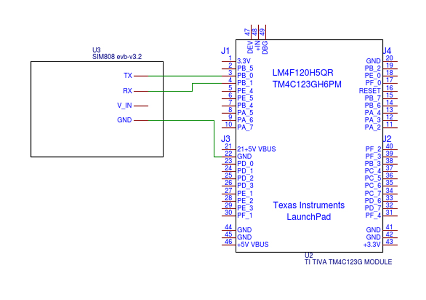
The below schematic shows the connectivity between the 2 evaluation boards:
Comments
BBCode Tags
| BBCode | Rendering |
|---|---|
| [b]bolded text[/b] | bolded text |
| [i]italicized text[/i] | italicized text |
| [u]underlined text[/u] | underlined text |
|
Auto link already enabled. |
http://example.org |
|
Auto image already enabled. |
 |
| [code=php]<?php echo 'Hello!'; ?>[/php] | |
| [quote]quoted text[/quote] | quoted text |
|
[list] [*]Entry 1 [*]Entry 2 [/list] |
|